- 24 -
optek-sensors AS56, Version 04.2010_1.2US, 15.04.2010
www.optek.com
Connection to converter C4000
Note!
Detailed information on the connection of the sensor to a C4000-series
converter is given in the instruction manual of the converter. There you can as
well find the corresponding wiring plans.
Connection to the
converter
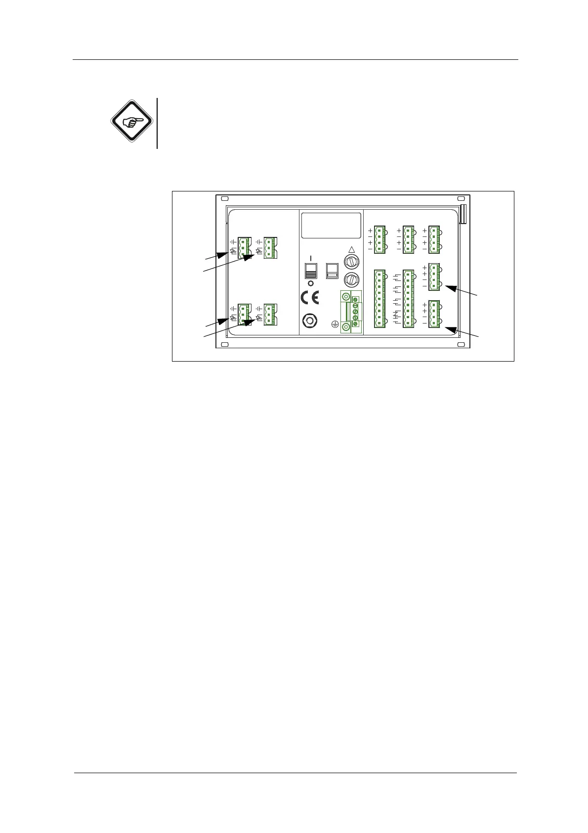
The following connections are on the back of the converter:
Fig. 17 Detector inputs and lamp outputs of the converter C4422
Letters stand for
• A -D Detector inputs
• E -F Connections for lamp outputs
The connections depend on the equipment of your converter and on how many
sensor you would like to connect.
20 2119
DETECTOR INPUTS
[C]
3
4
5
3
4
[D]
5
DETECTOR INPUTS
[A]
2
5
1
2
5
1
[B]
4 - 20 mA
OPTEK - DANULAT
REMOTE IN
R1
PA
M6
N
PE
L
R7
R8
RR
R4
R5
R6
R2
R3
115 / 230 V, 50 / 60 Hz, 50 VA
115 / 230 V, T 1,6 A
230V
!
24 V DC
IN 1, 2
acc. to
6
1031
MADE IN GERMANY
37
38
39
34
35
36
32
33
16
17
18
13
14
15
11
12
6
7
7
LAMP [F]
6
7
7
acc. to
cable
length
V DC
cable
length
0 / 4 - 20 mA
OUT 1, 2
24 V AC / DC
RELAY OUT
22
23
24
21
41
42
43
40
46
47
45
44
LAMP [E]
6
OUT 3, 4
V DC