- 28 -
optek-sensors AS56, Version 04.2010_1.2US, 15.04.2010
www.optek.com
Connection to converter 156
Note!
Detailed information on the connection of the sensor to the converter 156 is
given in the instruction manual of the converter. There you can as well find the
corresponding wiring plans.
Connection to the
converter
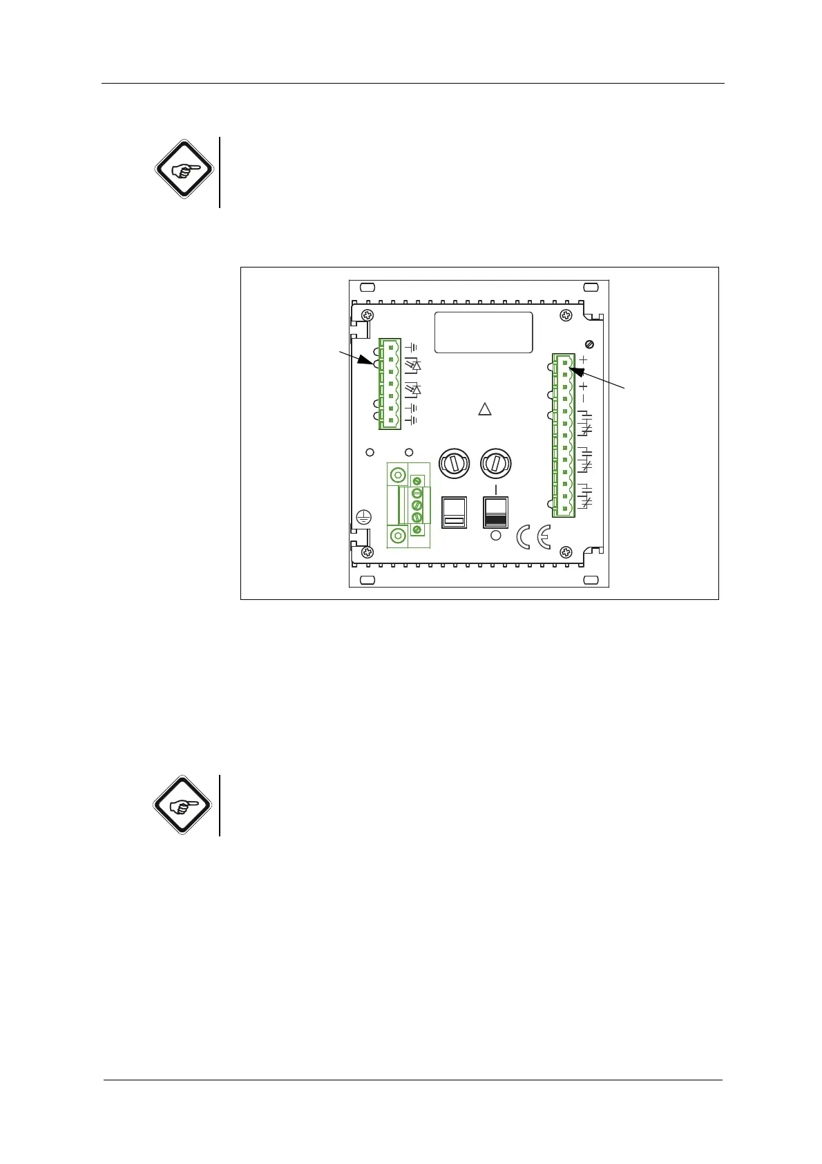
The following connections are on the back of the converter:
Fig. 20 Detector inputs and lamp outputs of the converter 156
Letters stand for
• G Detector inputs (5, 1, 2)
• H Lamp outputs (6, 7)
Connections depend on the equipment of your converter and on the number of
sensors you wish to connect.
Note!
Stick to the detector inputs and lamp outputs specified in table 10. Thus, danger
of mixing inputs and outputs up is minimized.
ALARM II
14
MADE IN GERMANY
OPTEK-DANULAT
N
PE
L
230V
LAMP AL
17
18
15
16
3
DETECTORINPUTS
5
5
4
50/60Hz, 30VA
230VAC, T0,315A
115VAC, T0,630A
115/230V
!
5
1
2
8
ALARM I
11
13
12
10
9
mA
VOLTAGE
6
7
LAMP
LAMP -
212019