- 29 -
optek-sensors AS56, Version 04.2010_1.2US, 15.04.2010
www.optek.com
Connection to converter 156
Tool • Screw driver
To be able to allocate the end splices unequivocally to the clamps of the
converter, each end splice is marked with the number of the correct clamp:
Detector cable to sensor
1 = white (A1) 2 = brown (A2) 5 = black (A5)
Lamp cable to sensor
6 = blue (6) 7 = brown (7)
Caution!
Lamp voltage must be adjusted to the cable length in order to compensate
voltage loss in the cable. Too low lamp voltage can lead to wrong measuring
results. Too high lamp voltage reduces the life of the lamp module considerably.
Follow the instructions in the instruction manual of the converter. During
operation, voltage at the lamp is 4.8 V DC.
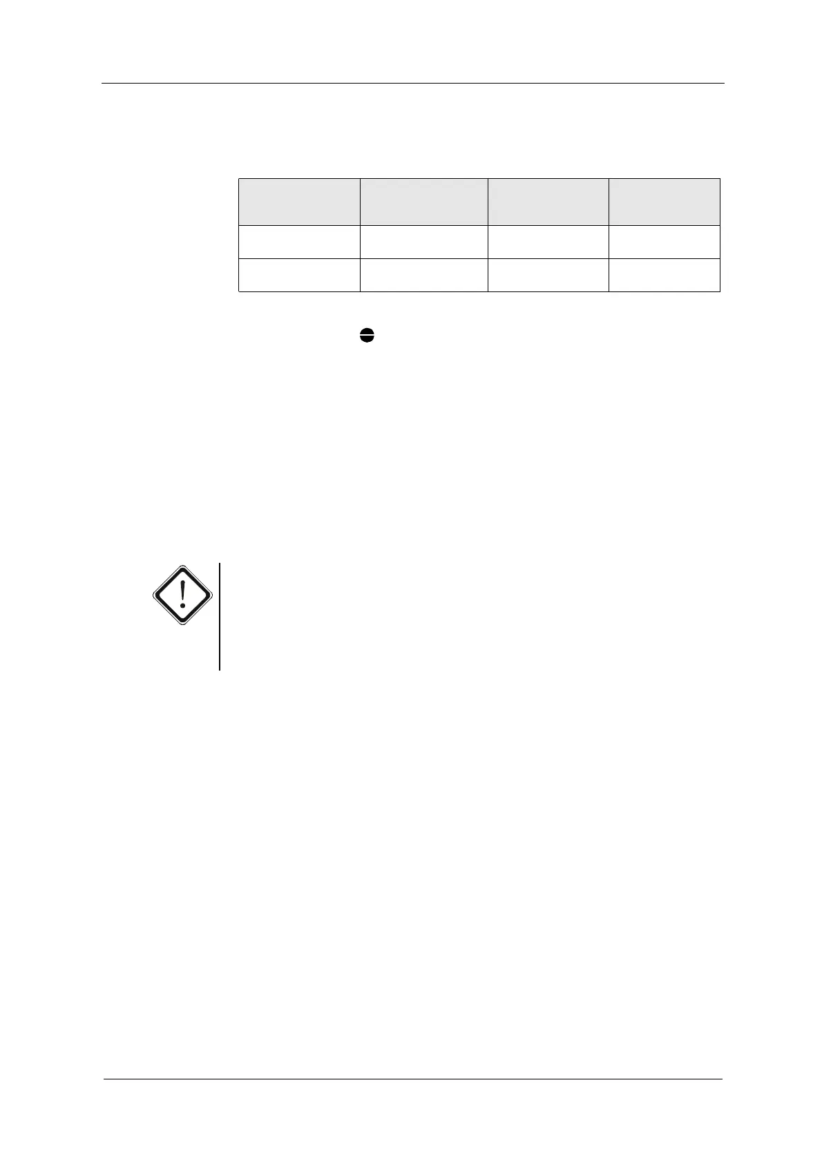
Tab. 10 Connections
Number of sensors
Sensor type
Connection to the
detector input of the
converter
Lamp output Cable length max.
1 sensor
AS56
Detector input (5, 1, 2) Lamp output (6, 7) 50 m
1 sensor
AF56
Detector input (5, 1, 2) Lamp output (6, 7)