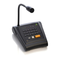
Microphone desk
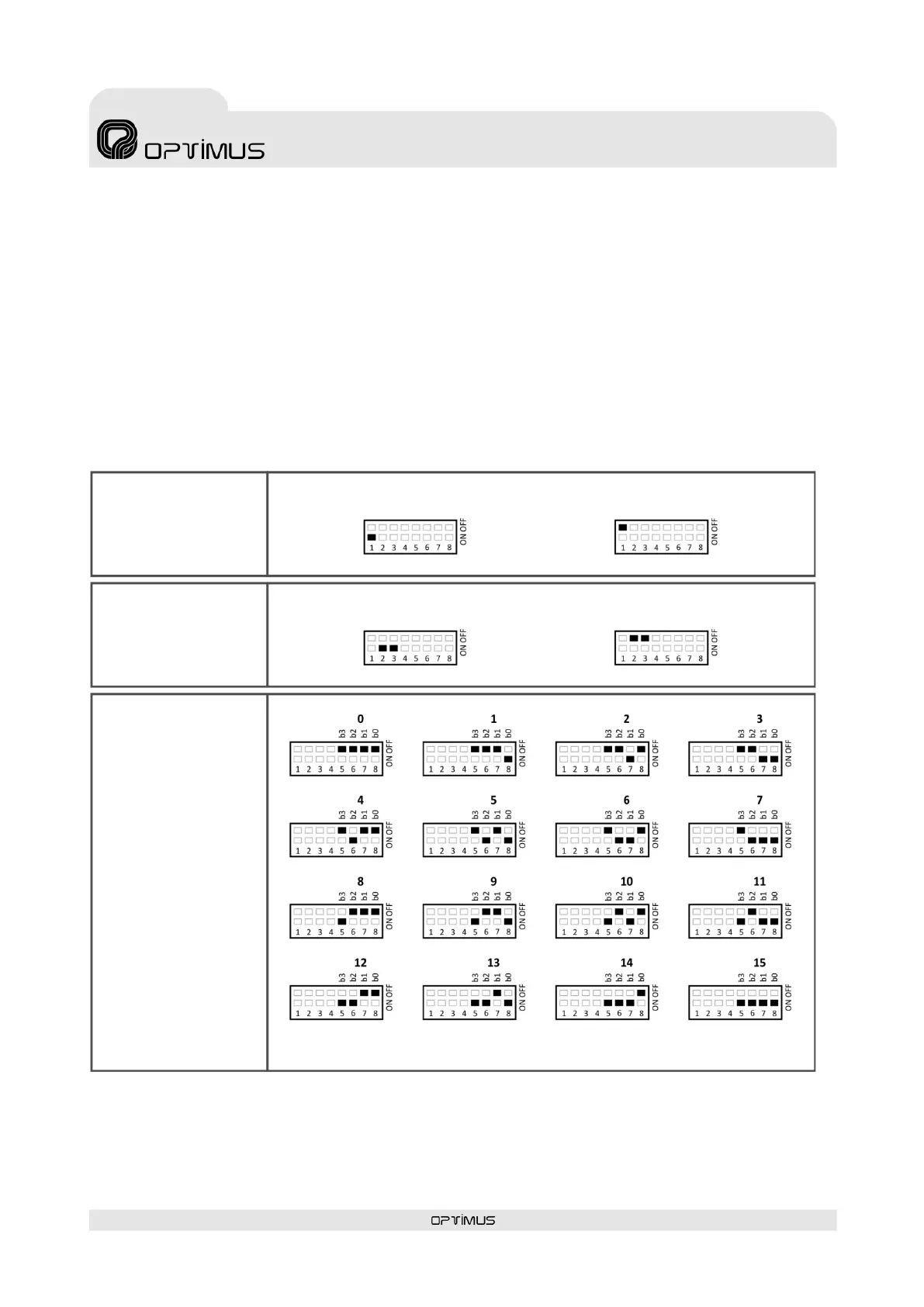
4. CONFIGURATION
Use the DIP switches on the back of the microphone to configure it:
DIP switch 1. RJ45 SHLD-GND LINK. Allows separating the PIN 8 and the shield of the RJ45 connectors from the MD-30C internal
ground (GND).
DIP switches 2 and 3. BUS CAN END. Configure DIP switches 2 and 3 to indicate the position on the CAN bus occupied by the MD-
30C (end element or intermediate element). If the microphone desk is the final bus element, set these DIP switches to ON. If it is an
intermediate element, set them OFF.
DIP switch 4. No used.
DIP switches 5, 6, 7 and 8. CAN ADDRESS. The microphone desk communicates with the COMPACT system through a CAN bus.
Ea ch MD-30C connected to the CAN bus must have a different communication address. Assign an address between 0 and 15.
OF PIN 8 AND SHIELD OF
RJ45 CONNECTORS
BUS CAN END
ON/OFF
ADDRESS
BUS CAN END: ON
BUS CAN END: OFF
FACTORY SETTINGS