Microphone desk
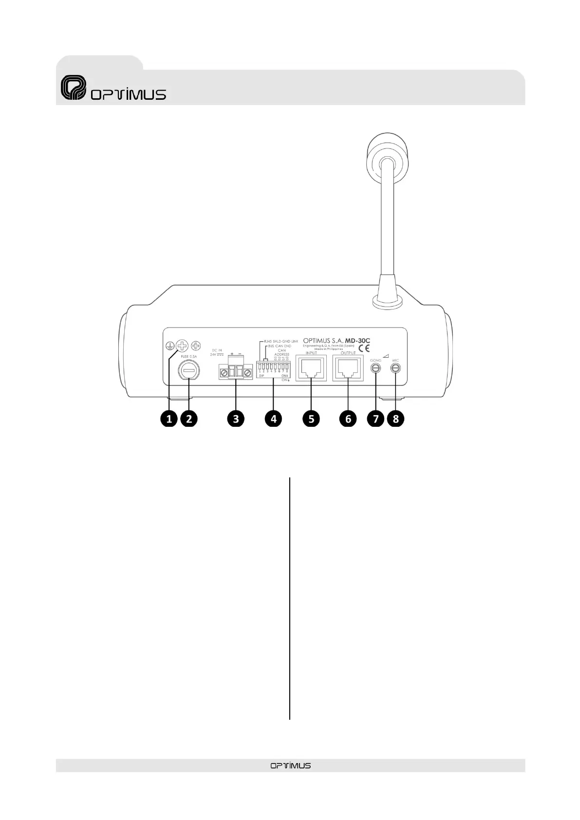
3. REAR VIEW
(1) Ground connection.
(2) Power supply fuse (0.5A).
(3) 24 VDC Power supply input (see section 5.1.).
(4) Configuration DIP switches (see section 4).
DIP switch 1. RJ45 SHLD-GND LINK. Allows separating the PIN
8 and the shield of the RJ45 connectors from the MD-30C
internal ground (GND).
DIP switches 2 and 3. BUS CAN END. Configure DIP switches
2 and 3 to indicate the position on the CAN bus occupied by
the MD-30C (end element or intermediate element). If the
microphone desk is the final bus element, set these DIP
s wi tches to ON. If it is an intermediate element, set them
OFF.
DIP switches 5, 6, 7 and 8. CAN ADDRESS. The microphone
desk communicates with the COMPACT system through a
CAN bus. Each MD-30C connected to the CAN bus must have
a di fferent communication a ddress. These DIP switches allow
you to assign this address.
(5) INPUT and (6) OUTPUT connectors
RJ45 Connectors. They are used to connect the equipment to
the COMPACT s ys te m. They transmit and receive the audio
and CAN data signals.
To connect them follow the section 5.2. Audio and CAN bus
connection.
The combination of the I NPUT a nd OUTPUT connectors a llow
the connection of several MD-30C desks (u p to a maximum of
16 desks) forming a BUS between elements. See section
5.2.2. CAN Bus and audio connection between several MD-
30C.
(7) GONG volume.
(8) Microphone volume.
Figure 2