EDFA optical amplifier – user manual
13
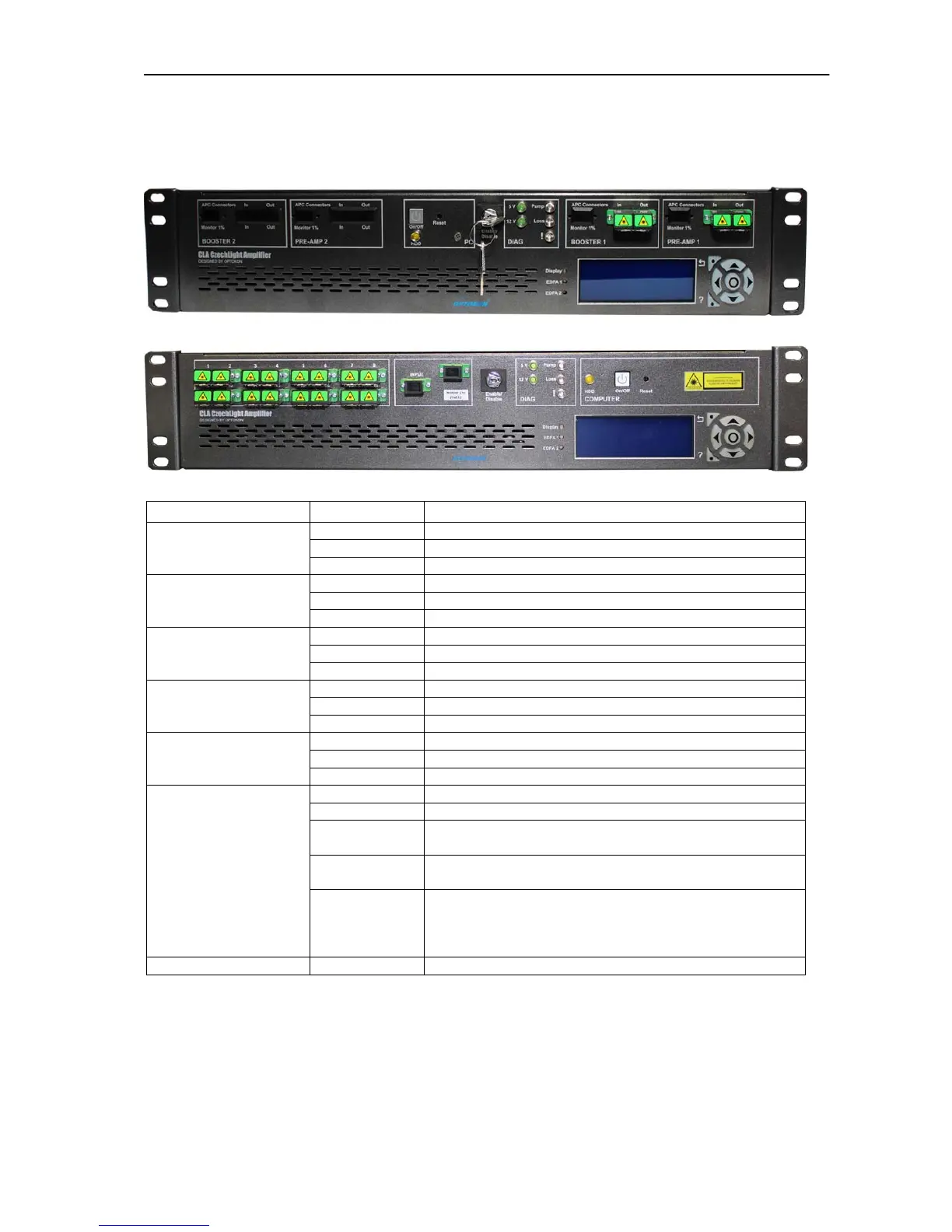
6 Mechanical design
6.1 Front panel
CLA-PB01F-NSC-D-AC
CLA-CA16-20-NSC-M-D-AC
Block on the panel Legend Description
IN Pre-Amplifier 1 Input
OUT Pre-Amplifier 1 Output
PRE-AMP 1
Monitor 1% Monitor of Pre-Amplifier 1 input (optionally)
IN Booster Amplifier 1 Input
OUT Booster Amplifier 1 Output
BOOSTER 1
Monitor 1% Monitor of Booster Amplifier 1 input (optionally)
IN Pre-Amplifier 2 Input
OUT Pre-Amplifier 2 Output
PRE-AMP 2
Monitor 1% Monitor of Pre-Amplifier 2 input (optionally)
IN Booster Amplifier 1 Input
OUT Booster Amplifier 1 Output
BOOSTER 2
Monitor 1% Monitor of Booster Amplifier 1 input (optionally)
ON/OFF ON/OFF button PC
Reset Reset button PC
COMPUTER
HDD HDD LED PC
5V Green LED indicates 5V
12V Green LED indicates 12V
Pump
Blue LED indicates active pump diode – the amplified
optical signal is at the output ports
Loss
Yellow LED indicates LOSS of input/output power alarm
(chapter 13)
DIAG.
!
RED LED indicates EDFA critical alarm –
temperature of pumping diodes or module is out of
range, the pumping current exceeds limit for end of
life current (chapter 13)
KEY Enable/Disable Amplifier ENABLE/DISABLE
WARNING:
Use only APC connectors (chapter 2.2)
Optical connector must be clean (chapter 2.2)
In case of active RED LED (EDFA alarm) - switch KEY to the Disable
position.