DRAFT
Proprietary and Confidential
26 Acme Packet 1100 Hardware Installation Guide
SYSTEM INSTALLATION
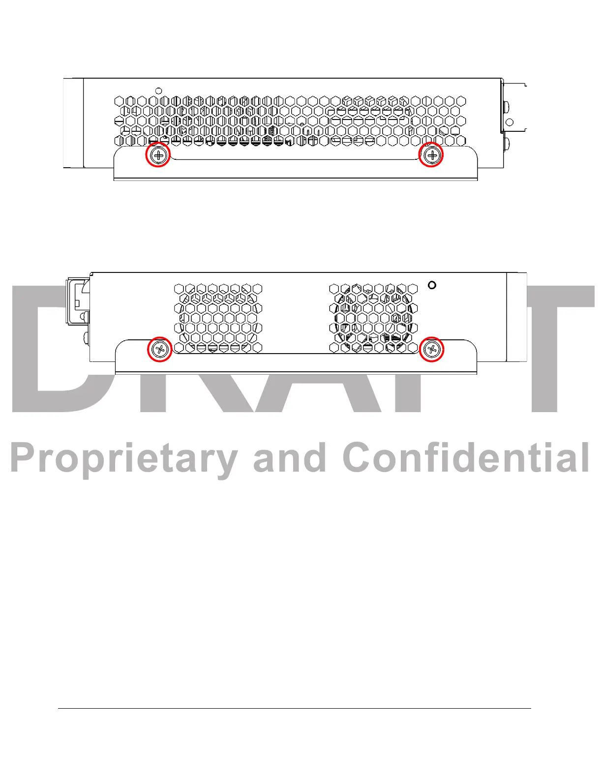
2. On the right side of the chassis, align the holes in the wall bracket with the holes
at the base of the chassis as shown.
Figure 4 - 6. Wall Bracket Mount Points on the Right Side of the Acme Packet 1100
3. Insert a #6-32 5/16” screw and washer into each of the holes and then use a
Phillips screwdriver to hand-tighten each screw to secure the wall bracket to the
chassis.
4. On the left side of the chassis, align the holes in the wall bracket with the holes
at the ba
se
of the chassis as shown.
Figure 4 - 7. Wall Bracket Mount Points on the Left Side of the Acme Packet 1100
5. Insert a #6-32 5/16” screw and washer into each of the holes and then use a
Phillips screwdriver to hand-tighten each screw to secure the wall bracket to the
chassis.
6. Ensure that there is enou
gh
room to access the front and back panel of the
chassis for purposes of reviewing front/back panel LEDs and inserting/removing
cables from the back panel.
7. Ensure that there is enough room on either
side of
the chassis for adequate
airflow to prevent overheating.
8. The illustration below shows relevant dimensions fo
r use in preparing the
surface on which to install the Acme Packet 1100 chassis. Pre-drill holes to
accommodate the screws, washers and anchors for each bracket that will secure
the chassis bracket to the surface. Insert customer-supplied
 Loading...