Orban 5950 Technical Manual Installation 2-21
Optically Isolated Remote Control Connections
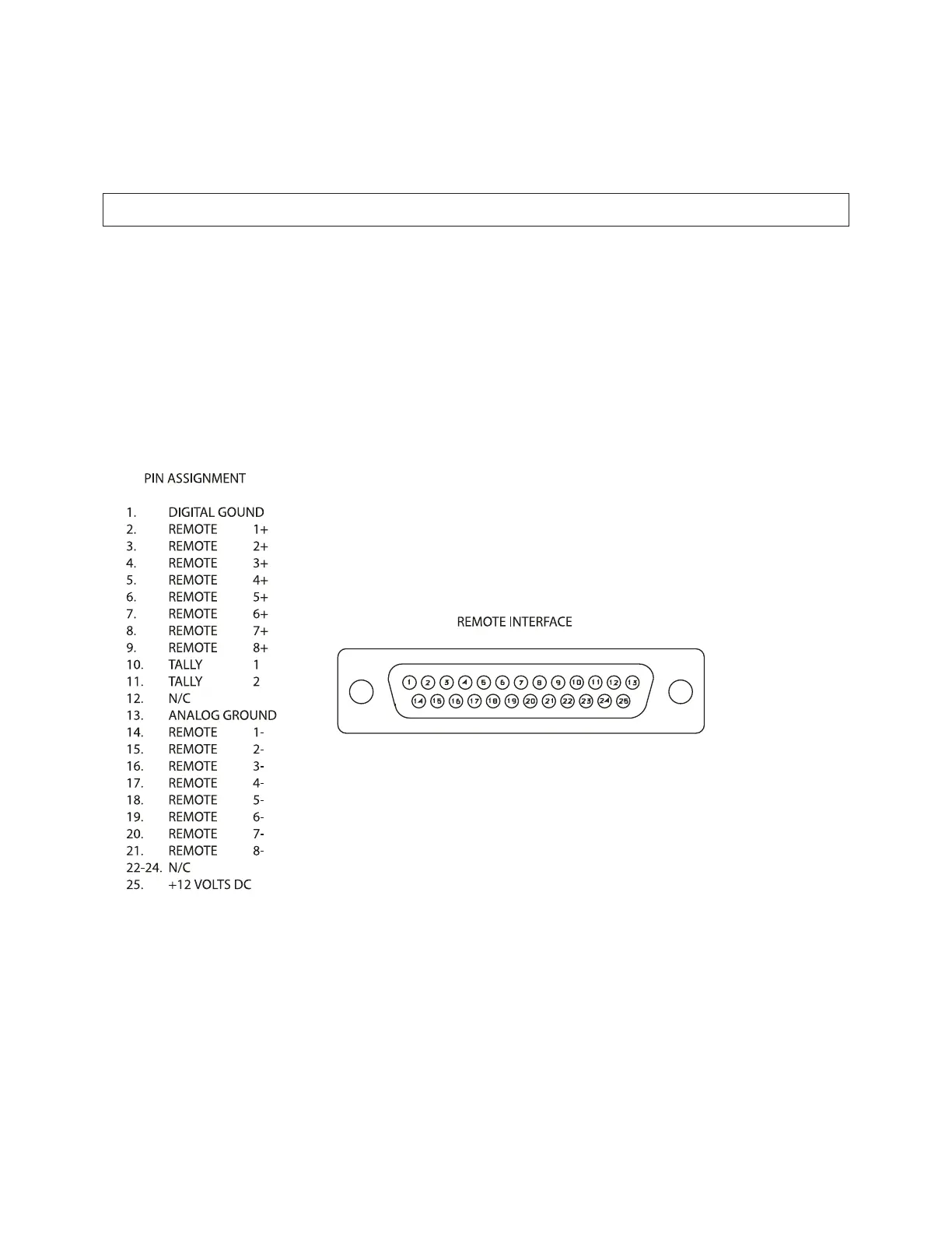
These are terminated in a type DB-25 male connector located on the rear panel. It is wired according to the
diagram below on the following page.
To select the desired function, apply a 5-12V AC or DC pulse between the appropriate Remote Interface terminals.
The () terminals can be connected together and then connected to power common at pin 1 to create a Remote
Common. A current limited +12VDC source is available on pin 25. If you use 48V, connect a 2k: r10%, 2- watt
carbon composition resistor in series with the Remote Common or the (+) terminal to provide current limiting.
In a high-RF environment, these wires should be short and should be run through foil-shielded cable, with the
shield connected to CHASSIS GROUND at both ends.
)LJXUH-:LULQJWKH-SLQ5HPRWH,QWHUIDFH&RQQHFWRU