Orban 5950 Technical Manual Technical Data 6-5
Transmission Levels
The transmission engineer is primarily concerned with the peak level of a program to prevent overloading or over-
modulation of the transmission system. This peak overload level is defined differently, system to system. In FM
modulation (FM / VHF radio and television broadcast, microwave or analog satellite links), it is the maximum-
permitted RF carrier frequency deviation.
In AM modulation, it is negative carrier pinch-off. In analog telephone / post / PTT transmission, it is the level
above which serious crosstalk into other channels occurs, or the level at which the amplifiers in the channel
overload. In digital, it is the largest possible digital word. For metering, the transmission engineer uses an
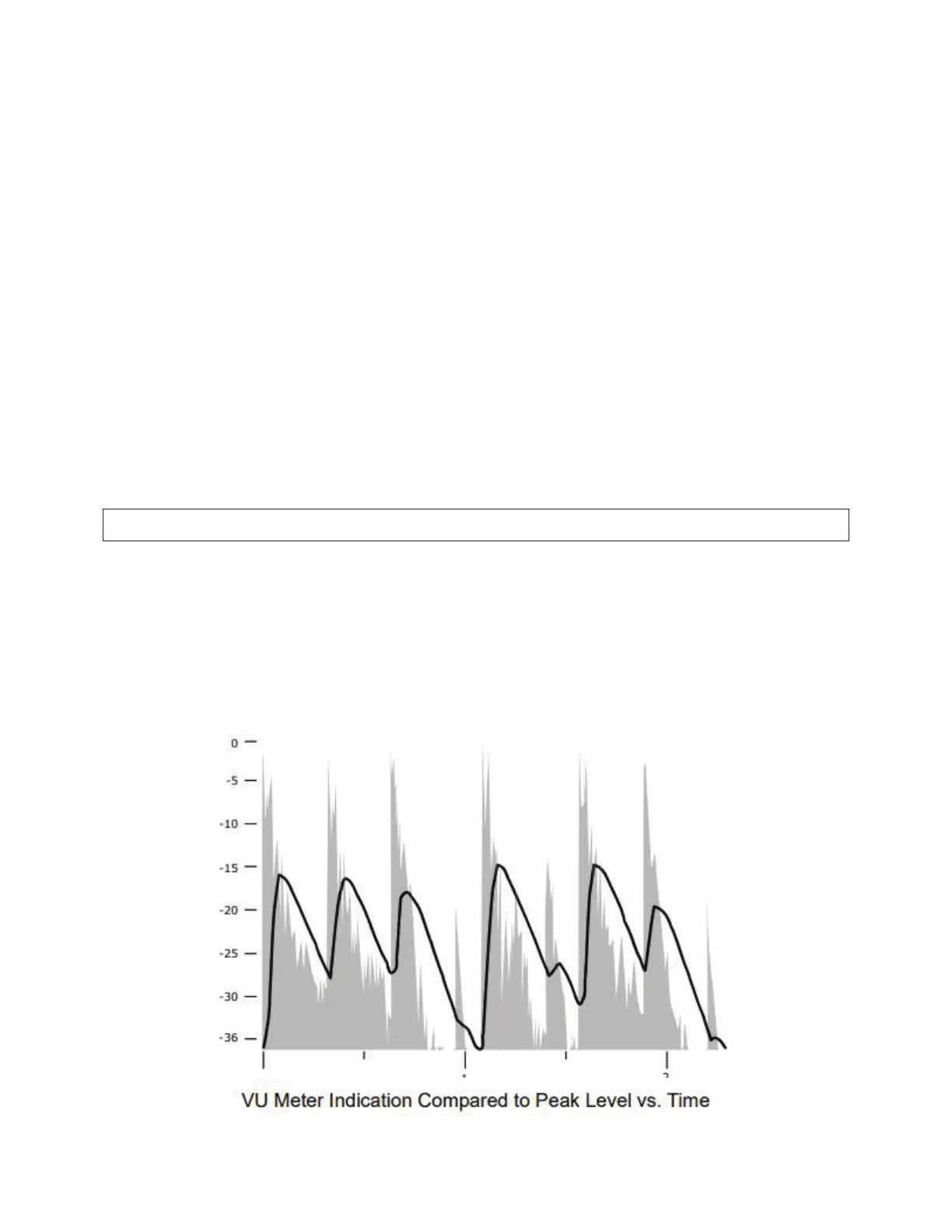
oscilloscope, absolute peak-sensing meter, calibrated peak-sensing LED indicator, or a modulation meter. A
modulation meter usually has two components—a semi-peak reading meter (like a PPM) and a peak-indicating
light, which is calibrated to turn on whenever the instantaneous peak modulation exceeds the overmodulation
threshold.
Line Up Facilities
Metering of Levels and Subjective Loudness
The meters on the 5950 show left/right input and output levels and composite modulation. Left and right input
level is shown on a VU-type scale (0 to –40 dB), while the metering indicates absolute instantaneous peak (much
faster than a standard PPM or VU meter). The input meter is scaled so that 0 dB on the scale corresponds +27 dBu,
which is the absolute maximum peak level that the 5950 can accept. If you are using the AES3 digital input, a full-
scale digital word corresponds to the 0 dB point on the 5950’s input meter.