OPERATING INSTRUCTIONS
Volts Cord length Amps Gauge needed Amps Gauge needed
115/120V 25 ft 0 - 6 18 10 - 12 16
6 - 10 18 12 - 16 14
115/120V 50 ft 0 - 6 18 10 - 12 16
6 - 10 18 12 - 16 14
115/120V 100 ft 0 - 6 16 10 - 12 14
6 - 10 14 12 - 16 not recommended
115/120V 150 ft 0 - 6 14 10 - 12 12
6 - 10 12 12 - 16 not recommended
Table 1 Extension Cord Requirements
Inspecting the Chain
Always inspect an incoming cutting chain and review any
problems with owner or user. Always check for proper
installation of tie straps and/or reversed drive links.
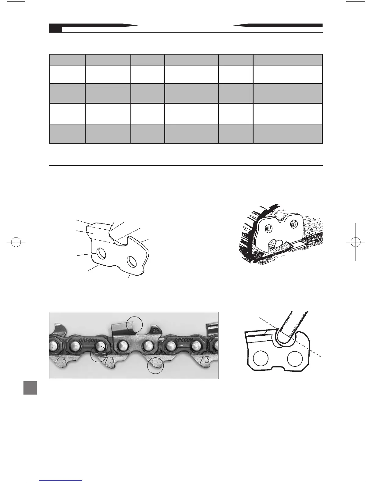
How a Cutter Works
A. Depth gauge
(controls bite of
the cutter).
B. Working corner
(slices the cross
grain – does most
the work).
C. Top plate edge (lifts out chips after cross grain
has been cut).
D. Heel and toe (support cutter while working).
Top Plate
Side Plate
Rivet Hole
D. Heel
E. Toe
C. Top Plate
Edge
B. Working Corner
A. Depth
Gauge
Parts of a Cutter
Gullet
Note: For proper side plate angle,
do not grind the gullet deeper
than where the grinding wheels’
radius meets the flat of the wheel.
10