ASSEMBLY INSTRUCTIONS
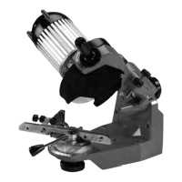
2. For correct bench positioning, use the
notch on the base of the grinder (see inset
photo, Figure 1, page 7).
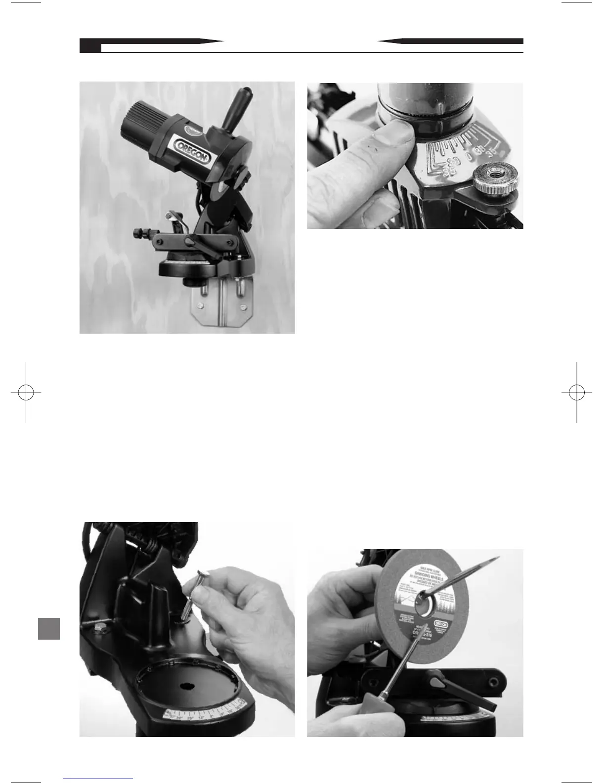
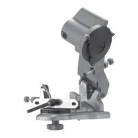
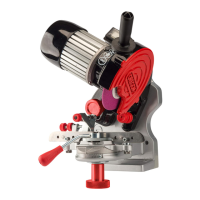
3. To mount the unit to a workshop wall, use
optional wall/vise mount fixture assembly,
part no. 109430 (see Figure 2). The optional
wall/vise mount fixture can be used with a
common industrial sized bench vise.
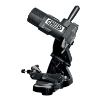
4. To mount the unit to a stand use nuts and
bolts (see Figure 3).
Note: The bar-mounted grinder units
come assembled with a spacer that is
required to sharpen standard type-chains
(see Figure 4). This spacer must be
removed to sharpen all other types of chain.
B. Selecting and Mounting the Grinding
Wheel:
1. For the appropriate size grinding wheel
see table 2 on page 17.
2. Make sure that the grinding wheel is in
perfect condition. Hang the wheel by the
center hole and tap it lightly with a metal
object on one side near the perimeter. If a
flat tone is heard it may be cracked or
broken. Do not use! (see Figure 5 ).
3. Remove the black plastic shield from
the unit by first removing the position lock
screw, then the shield (see Figure 6, page 9).
Figure 2
Figure 3
Figure 4
Figure 5
8