OPERATING INSTRUCTIONS
Grinding A Chain
Immediately unplug the
power cord if the motor
does not turn the grind wheel
when the grinder power switch
is in the “on” position. Refer to
page 7: **Grounding Instructions.
1. For best results it is recommended that
the chain be clean before grinding.
2. Always wear approved eye protection
during all steps of the grind operation and
when the grind wheel is in motion.
3. Grind all cutters of the same type (left or
right) before positioning the grinding wheel
to the opposite side.
4. When changing the grind position, make
sure the unit is turned to the “off” position
(“o” Figure 15, page 12) and the wheel
has come to a full stop before making
any adjustments.
5. To avoid overloading the motor and prevent
damage to the saw chain, remove only the
minimum amount of material necessary
and do not grind any one tooth for too
long a period.
6. Do not use cooling liquids while grinding.
7. Replace worn grinding wheels when the
diameter of the wheel reaches 70mm (2.8”).
Note: Always remember to turn the grinder
to the “off” position when not in use.
D. Low-Profile Grinding for
Bench/Wall/Stand Mounted
Workstations:
There is risk of serious
personal injury for chain
saw operators or bystanders from improperly
sharpened saw chain. Read and follow all
manufacturer’s instructions for your chain saw.
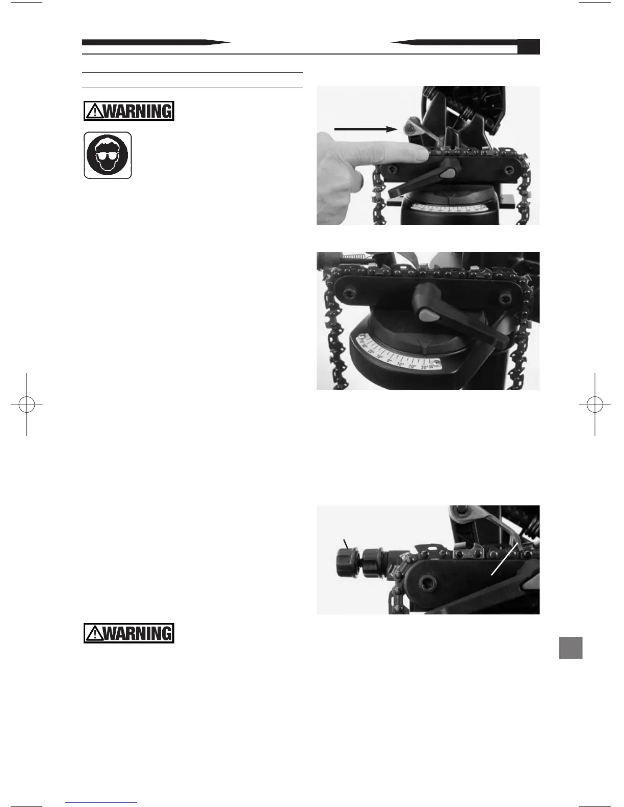
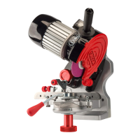
1. Position the saw chain to be ground onto
the vise (see Figure 10).
2. Use reference table 2 page 17 , select type
of chain, rotate vise to appropriate angle
for left and right cutters (see Figure 11 ).
Note: All adjustments must be made prior
to applying power to the unit.
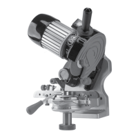
3. Set the chain stop into the desired grind
position (see Figure 12 ).
4. Lower the grind head into the grind
position and adjust depth adjustment
knob (see Figure 13, page 12).
5. After all adjustments have been made,
engage the vise clamping feature by
depressing the red push button and rotating
the adjustment knob in a clockwise direction
until the saw chain is firmly held in position
for grind operation (see Figure 14, page 12).
Figure 11
Chain
Direction
Figure 10
Figure 12
11
Chain Stop
Adjustment
Knob
Chain
Stop