Note: Inspect the shield for cracks or
obvious defects prior to reinstallation.
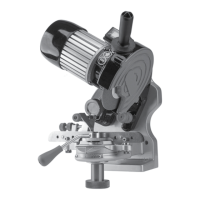
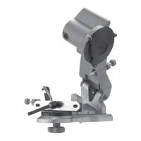
4. Remove the large plastic grind wheel outer
retaining flange nut (see Figure 7).
5.Position the desired grind wheel securely
onto the shaft arbor fitting and reinstall the
washer and outer retaining flange nut (see
Figure 7). Tighten by hand only, being
careful not to over-tighten the flange nut.
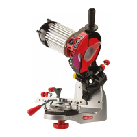
6.Reinstall the plastic shield and secure with
the position lock screw (see Figure 8).
Note: Do not over-tighten the lock screw.
7.Connect the plug to a serviceable electrical
outlet, move to the side of the unit, and
turn the grinder to the on position (see
Figure 15, page 12).
8. From a safe distance at the side of the unit,
observe the grinding wheel as it turns to
make sure it does not wobble.
Replace the wheel if necessary.
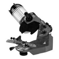
C. Dressing The Grinding Wheel:
1. With the grinder in the off position (see
Figure 15, page 12), check the profile of the
wheel using the template (item 10, page 6).
If necessary, dress the wheel (power on)
using quick, light strokes with the brick to
form the desired profile (see Figure 9).
2. Turn the unit off and re-check the wheel
profile. If necessary, redress the wheel until
the desired profile is obtained.
ASSEMBLY INSTRUCTIONS
Figure 7
Figure 8
Figure 9
9
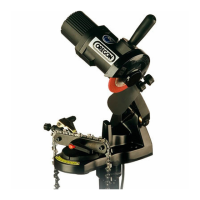
Figure 6
Note:
Place the washer’s
flat side flush against
the grind wheel.