Connection
56
3 DC power input type
Electrical wire size
Connector Terminal symbol Recommended wire size
CN1
+24V, 0V, HWTO1+, HWTO1−,
HWTO2+, HWTO2−, EDM+, EDM−
Stranded wire or solid wire AWG26 to 20 (0.14 to 0.5 mm
2
)
CN4
+, −, MB1, MB2 Stranded wire or solid wire AWG24 to 16 (0.2 to 1.25 mm
2
)
Stranded wire or solid wire AWG18 to 16 (0.75 to 1.25 mm
2
)
CN7 − Stranded wire or solid wire AWG26 to 20 (0.14 to 0.5 mm
2
)
4-2 Connecting the control power supply
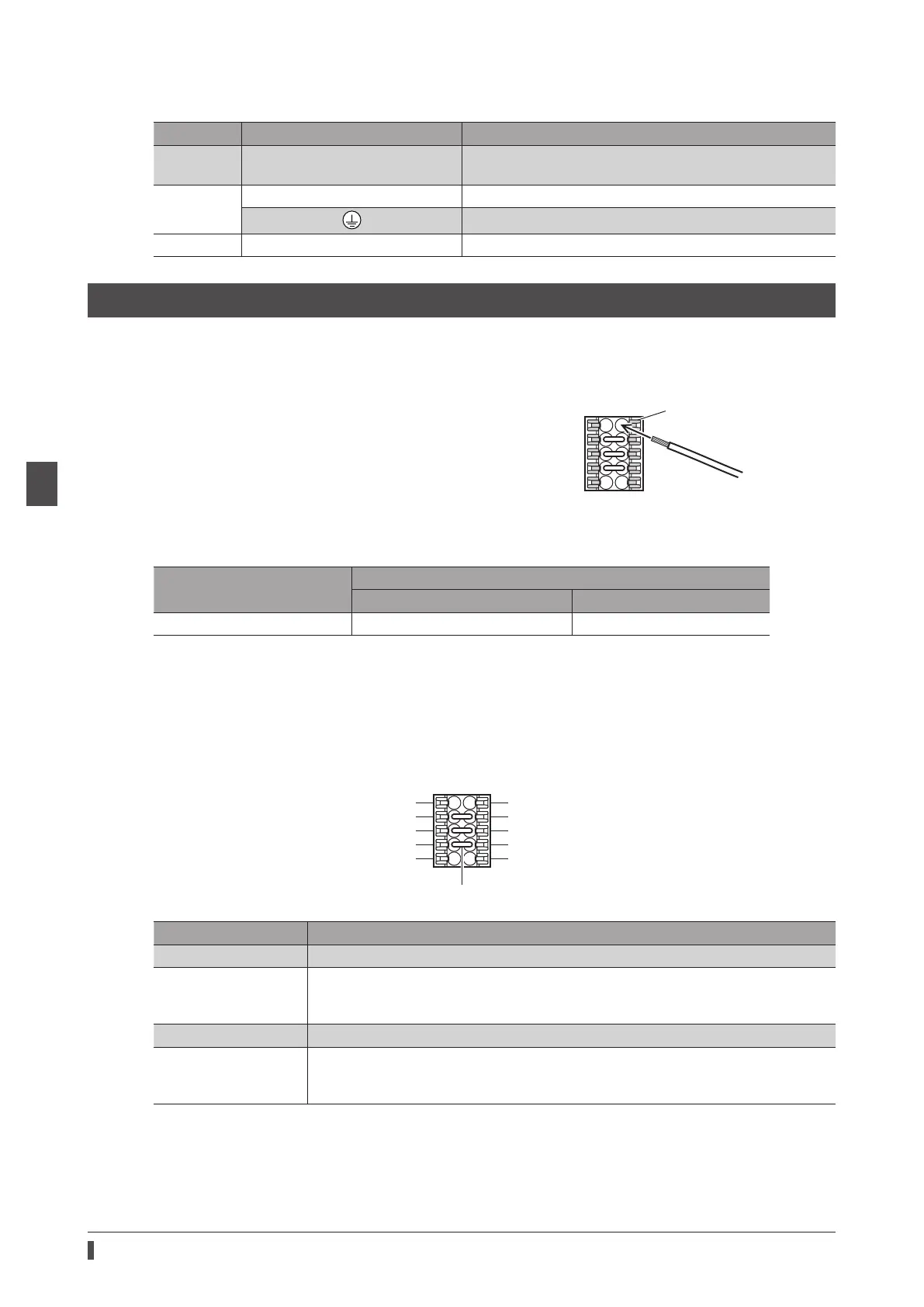
Wiring method of CN1 connector
•
Applicable lead wire: AWG26 to 20 (0.14 to 0.5 mm
2
)
•
Stripping length of wire insulation: 7 mm (0.28 in.)
1. Strip the insulation of the lead wire.
2. Insert the lead wire while pushing the button of the orange color
with a slotted screwdriver.
3. After having inserted, release the button to secure the lead wire.
Lead wire
Button of the orange color
Power supply current capacity
Input power supply voltage
Power supply current capacity
Without electromagnetic brake With electromagnetic brake
24 VDC±5% *1 0.15 A 0.4 A *2
*1 When an electromagnetic brake motor is used, if the wiring distance between the motor and the driver is extended
to 20 m (65.6 ft.) using our cable, the input voltage is 24 VDC±4%.
*2 The
AZM46
type is 0.23 A.
Pin assignment
There are two terminals for 0 V: One for control power supply and the other is for internal connection. Check each
position in the gure and the table shown.
+V
TO1
-
TO2
-
EDM+
HWT
HWT
0V *2
EDM
-
Sign Description
+24V, 0V *1 Connects the control power supply.
HWTO1+, HWTO1−
HWTO2+, HWTO2−
Connects switches or the EtherCAT master.
If the power removal function is not used, connect a jumper wire (included) between the
terminals as shown in the gure.
EDM+, EDM− Connects the EtherCAT master.
+V, 0V *2
These are for internal connection. Do not connect anything.
If the power removal function is not used, connect a jumper wire (included) between the
terminals as shown in the gure.
 Loading...