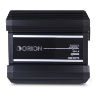
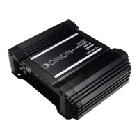
Do you have a question about the Orion Xtreme Series and is the answer not in the manual?
A regulated power supply for improved sound quality and amplifier damping.
Two slots for system flexibility, accepting crossover or signal processor modules.
Signal can be routed via DIN or RCA, with options for internal crossover or full range output.
Allows bypassing internal gain stage for master/slave control or better S/N ratio.
Provides easy access to crossover ports and signal jumpers for module changes.
Connectors for larger wire gauge, simplifying installation and improving performance.
Machined aluminum heat sink for efficient cooling and component longevity.
Configuration for stereo speakers and bridged mono woofer using passive crossovers.
Connectors for linking amplifiers or using with previous ORION components.
Reinforced boards with nickel plating for enhanced reliability and durability.
On-board power for external processors, eliminating grounding issues.
Matched outputs for reduced distortion, improved sound quality, and thermal stability.
Allows higher power output at lower impedance loads without protection activation.
One amplifier drives full range speakers; factory configured with 2Ω stereo impedance.
Bridged mono for woofer with 12 dB/octave low-pass filter; 4Ω bridged mono impedance.
Mixed-mono for woofer and stereo for speakers, requires correct passive crossovers.
Bi-amplified system with master bridged mono and slave high-pass stereo operation.
Bypasses high-frequency amp gain for better S/N ratio; 2Ω stereo, 4Ω bridged mono.
Master/slave for woofers, 4Ω bridged mono, slaves bypassed for tuning and S/N.
Tri-amp system with master summed mono low-pass, slave 1 bandpass, slave 2 high-pass.
Default configuration uses RCA inputs, AUX parallel, DIN AUX disabled, gain stage enabled.
RCA AUX paralleled to RCA inputs, DIN inputs paralleled, DIN AUX disabled, gain stage enabled.
RCA AUX can be full range or filtered through internal modules.
Left/Right AUX RCAs filtered through internal modules and gain stage.
Single jumper sums amplifier output; left/right inputs are internally summed.
Slots configured in series for 12dB/octave filters (high/low-pass, bandpass); 24dB/octave possible.
Pick a ventilated location, mount flat, avoid tight spaces, and ensure air movement.
Details on using 8 gauge wire for power and ground, fuse placement, and battery connections.
Explains power/ground via 8 ga connector and speaker connections via 12 ga connector.
Describes wiring for stereo operation, noting the lowest recommended impedance is 2Ω.
Combining left/right channels for single channel amplification, doubling output capability for mono or mixed-mono.
Using right negative and left positive outputs for mono, caution on impedance and input summing.
Woofer in mono, speakers in stereo; requires correct passive crossovers and frequency non-overlap.
Details RCA signal input range, main inputs, AUX programmability, and max RCA output.
DIN signal range, AUX programmability, max DIN output, and 15V phantom power supply.
Steps for adjusting gain with no accessories like equalizers or crossovers.
Steps for adjusting gain when using accessories like equalizers or crossovers.


