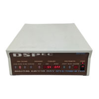
DSPEC 50
®
and DSPEC 502
®
Digital Gamma-Ray Spectrometer User’s Manual 932502G / 0618
6.1.1. Inputs and Outputs
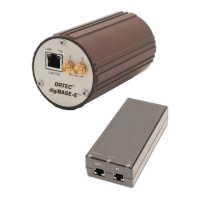
Note that each chassis (DSPEC 50 or DSPEC 502) has only one ac input power module, USB
connector, Ethernet connector, SD card slot, and RESET port. Otherwise, each MCB has the
following set of inputs and outputs.
15
DIM Multi-pin connector (13W3) carries the following:
! Preamp Power 1 W maximum (+12V, !12V, +24V, !24V, 2 GND)
! Analog In Normal amplifier input
! Inhibit For TRP or gate
! Battery Power (5 V–12 V) for DIM
! HV control
! SMART-1 HPGe detector control
NOTE NaI detectors can be used with the DSPEC 50 only in conjunction with the ORTEC
DIM-POSNAI interface module and the rear-panel DIM connector.
INPUT Rear-panel BNC accepts preamplifier signals of either polarity, with rise times less
than the selected flat top setting and exponential decay time constant in the range of 40 ìs to
infinity (including TRP and pulsed-optical [POF] preamplifiers). Input impedance >500 Ù, input
is dc-coupled and protected to ±12 V.
GATE IN Rear-panel BNC accepts 3.3 V (5 V tolerant) slow-positive NIM input; software-
selectable as off, coincidence, or anticoincidence. ADC GATE signal must precede and overlap
the flat top region by 0.5 ìs, and extend beyond the flat top region by 0.5 ìs. InSight Oscillo-
scope allows easy alignment of the ADC GATE signal with the digital output pulse. The
Advanced models have configurable coincidence and gate timing options to align the gate to the
peak detection time and have a counter associated with TTL pulses on the Gate port.
INHIBIT IN Rear-panel BNC connector accepts 3.3 V (5 V tolerant) reset signals from TRP or
POF preamplifiers. Positive NIM logic or TTL level can be used. Inhibit input initiates the
protection against distortions caused by preamplifier reset. This includes turning off the baseline
restorer, monitoring the overload recovery, and generating the pileup reject and busy signals for
the duration of the overload. These last two signals are used internally to provide information to
the dead-time correction circuitry.
PREAMP POWER Rear-panel, 9-pin D connector; provides ±24 V and ±12 V for preamp-
lifier power.
15
On the DSPEC 502, some input labels are abbreviated due to space constraints; e.g., SAMPLE READY IN is
abbreviated as SMPL RDY, CHANGE SAMPLE IN becomes CHG SMPL, and so on.
70