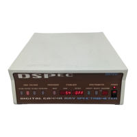
932502G / 0618 67. SPECIFICATIONS
HIGH VOLTAGE (one HV module per chassis)
! Positive 0–5 kV Rear-panel SHV connector, 500 V–5 kV. Computer controlled. Only
active when the unit is set for positive bias.
! Negative 0–5 kV Rear-panel SHV connector, 500 V–5 kV. Computer controlled. Only
active when the unit is set for negative bias.
SHUTDOWN IN Rear-panel BNC turns off the bias supply voltage when the detector is warm.
Software-selectable ORTEC or TTL mode (SMART-1 detectors auto-select the SMART shut-
down mode). In ORTEC mode, the detector Bias Shutdown must be connected to this input or
the high voltage will not turn on.
CHANGE SAMPLE OUT Rear-panel BNC connector, TTL compatible. The output signal is
configurable with the Advanced models as described in Section 4.12.
SAMPLE READY IN Rear-panel BNC connector accepts TTL level signal from sample
changer. The Advanced models have a counter associated with TTL pulses on the Sample
Ready port.
ETHERNET Standard 10/100 Mbit Ethernet connection. Link and Activity LEDs are inte-
grated into the connector. Use dynamic or static IP addressing.
USB Emulates a USB connection. ORTEC CONNECTIONS software supports up to 255 USB-
connected devices per computer.
SD SecureDigital™ (SD) memory card slot for uploading a maximum of 9 optional .JPG-format
image files.
RESET For system maintenance performed in conjunction with the ORTEC Global Service
Center.
6.1.2. Electrical and Mechanical
Dimensions 42.6 cm W × 35.6 cm D × 15.3 cm H (16.8 in. W × 14.0 in. D × 6.0 in. H).
Weight 11 kg (24.3 lbs).
Operating Temperature Range 0EC to +50EC, including touchscreen.
71