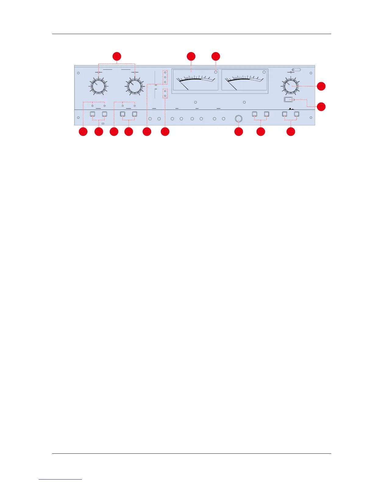
Figure 3-4 Amplifier Panel
[1] Input Level Knobs The outer knob adjusts the line input signal level. The inner knob adjust the microphone
input signal level.
[2] VU Meters The VU meters indicate the record and reproduce levels of the associated channels. The
VU meters illuminate when the machine is turned on.
[3] Peak Level Indicators (LED) Each VU meter has a PEAK level indicator which illuminates when the signal reaches a level
equivalent to 1040 nWb/m.
[4] SRL Indicator This illuminates when the SRL button is pressed.
[5] Output Level Knob The outer knob adjusts CH1 output signal level. The inner knob adjusts CH2 output signal
level.
[6] SRL Switch This switch selects the Standard Reference Level (SRL) of the output level. When this
switch is pressed, the output level is set to the SRL (factory setting: +4 dB).
[7] Monitor Button This button selects the monitor signal source. When this button is set to SOURCE position,
all the OUTPUT connectors and VU Meters receive the signal present at the INPUT
connector. When this button is set to TAPE position, the signal reproduced with the Repro
Head is output.
[8] Test Oscillator Buttons Pressing one of these buttons activates the test oscillator. The selectable oscillator
frequencies are 1 kHz and 10 kHz.
[9] Monitor Phone Jack This is the monitoring Head Phone Jack. Load Impedance is 8
[10] SEL·REP Mode Button If the Monitor button is set to TAPE position and the SEL·REP Mode button is pressed, all
the OUTPUT connectors and VU Meters receive signals reproduced by the Record head.
[11] SEL·REP Indicator This indicator illuminates when the SEL·REP mode is selected.
[12] RECORD READY Buttons When these buttons are pressed, the machine enters into Ready mode. In Ready mode,
the machine enters Record mode when the RECORD and PLAY buttons are pressed. If
these buttons have not been depressed, the machine is set to SAFE. In Safe mode, the
machine cannot enter Record mode even if the RECORD and PLAY buttons are pressed.
[13] RECORD Mode Indicator This indicator illuminates when the machine is set to Record Ready mode.
[14] EQ indicator This indicator illuminates to show the selected EQ setting.
[15] REF FLUX indicator This indicator illuminates to show the selected Reference Flux Level.
MX-5050mkIV-2/BIII-2 Operation and Maintenance Manual
1999-02 17
 Loading...