Do you have a question about the OTARI MX-5050 and is the answer not in the manual?
Read and follow all safety and operating instructions. Heed all warnings on the device and in the manual.
Information on how to contact Otari Inc., Otari Corporation, Otari Europe GmbH, and Otari Singapore Pte., Ltd.
Details to include in correspondence for technical support and manual revisions.
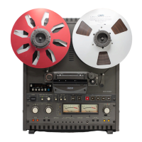
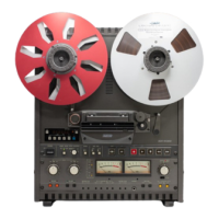
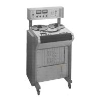
Description of the new MX-5050 Series tape recorders and their various models.
Guidance on the manual's organization, including section descriptions.
Explanation of type conventions, PCB assemblies, and bracket references used in the manual.
Procedure for unpacking and inspecting the MX-5050 tape recorder for damage.
Details on machine input/output connectors and transformerless balanced design.
Explanation of input/output connector pin assignments and optional transformers.
Configuration of switches on the rear panel for various machine functions.
Details on DIP switch settings for speed version, punch-in, and other functions.
Instructions for accessing and rotating PCB assemblies for BIII and MKIV-2 models.
Procedure for connecting the power cable and AC voltage connector replacement.
Guidelines for replacing fuses, emphasizing using the correct type and disconnecting power.
Steps to change the tape speed from High Speed to Low Speed on the BIII-2 model.
Procedure for changing equalization settings between NAB and IEC standards.
Identification and description of key parts of the tape transport mechanism.
Detailed explanation of each button, switch, and display on the transport control panel.
Description of the head types, track widths, and their composition.
Overview of controls, indicators, and jacks on the amplifier panel.
Identification of audio connectors, switches, and terminals on the BIII model.
Detailed pin assignments for the Parallel I/O connector and other interfaces.
Summary tables for transport, audio channel, and auto locator modes.
Explanation of various transport modes like Play, Record, Edit, and Cue modes.
Instructions for placing reels on the machine using different hub types.
Step-by-step guide for threading the tape from supply reel to take-up reel.
Procedures for playing back tracks, recording tracks, and punch-in/out operations.
Procedure for SEL-REP (Selective Reproduce) recording.
Using Fast Wind modes and monitoring tape audio with the Cue button.
Detailed steps for performing tape editing, including ready mode and splicing.
Adjusting tape speed ±20% for time-slot fitting or special effects.
Instructions for storing tape locations, search modes, and repeat play.
Using the built-in two-frequency test oscillator for level matching and alignment.
Suggested maintenance schedule for keeping the MX-5050 in peak operating condition.
Necessary procedure for demagnetizing heads and tape path components with caution.
Importance of regular cleaning for audio performance, slippage, and wear.
Instructions for lubricating the Capstan Motor bearing using Otari oil.
Procedures for accessing transport parts and adjusting brake torque for supply and take-up sides.
Steps to adjust the tape lifter position to ensure proper gap between tape and lifters.
Adjusting capstan motor speed and pitch control using an oscilloscope.
Procedure for adjusting pinch roller pressure against the capstan shaft.
Measuring and adjusting tape speed using a special test tape and frequency counter.
Instructions for adjusting the height of the reel table for proper reel placement.
Procedure for replacing head stacks and performing head position adjustments.
Adjusting head wrap to ensure proper tape approach and departure angles.
List of necessary tools, alignment tapes, and test equipment for audio alignment.
Adjustments for peak indicator level and test oscillator waveform/level.
Procedures for reproducing head azimuth, level, and equalization adjustments.
Adjustments for record bias level, record head azimuth, record level, and EQ.
Procedure for adjusting low frequency reproduce equalization.
Procedure for adjusting the SEL-REP level.
Technical details on track configuration, heads, motor, reel size, tape speed, and timing.
Specifications for input/output levels, equalization, frequency response, and signal-to-noise ratio.
Exploded view and parts list for the BIII model case assembly.
Exploded view and parts list for the BIII model chassis assembly.
Exploded view and parts list for the BIII model head assembly.
Exploded view and parts list for the BIII model reel assembly.
Exploded views and parts lists for pinch roller, capstan, and shifter assemblies.
Exploded views and parts lists for tension arm, impedance roller, and timer assemblies.
Exploded view and parts list for the BIII model control assembly.
Exploded view and parts list for the BIII model amplifier assembly.
Exploded view and parts list for the BIII model connector panel assembly.
Exploded view and parts list for the MKIV-2 model case assembly.
Exploded view and parts list for the MKIV-2 model chassis assembly.
Exploded view and parts list for the MKIV-2 model head assembly.
Exploded view and parts list for the MKIV-2 model reel assembly.
Exploded views and parts lists for MKIV-2 pinch roller, capstan, and shifter assemblies.
Exploded views and parts lists for MKIV-2 tension arm, impedance roller, and timer assemblies.
Exploded view and parts list for the MKIV-2 model control assembly.
Exploded view and parts list for the MKIV-2 model amplifier assembly.
Exploded view and parts list for the MKIV-2 amplifier connector assembly.
Exploded view and parts list for the MKIV-2 model connector panel assembly.
Schematic block diagram illustrating the signal flow and components of the MX-5050.
Flowchart to diagnose and resolve issues related to the tape transport mechanism.
Flowchart to diagnose and resolve issues related to the electronic circuits.