Section 2 Installation
2 - 4
May 1992
MX-5050 Operation and Maintenance Manual
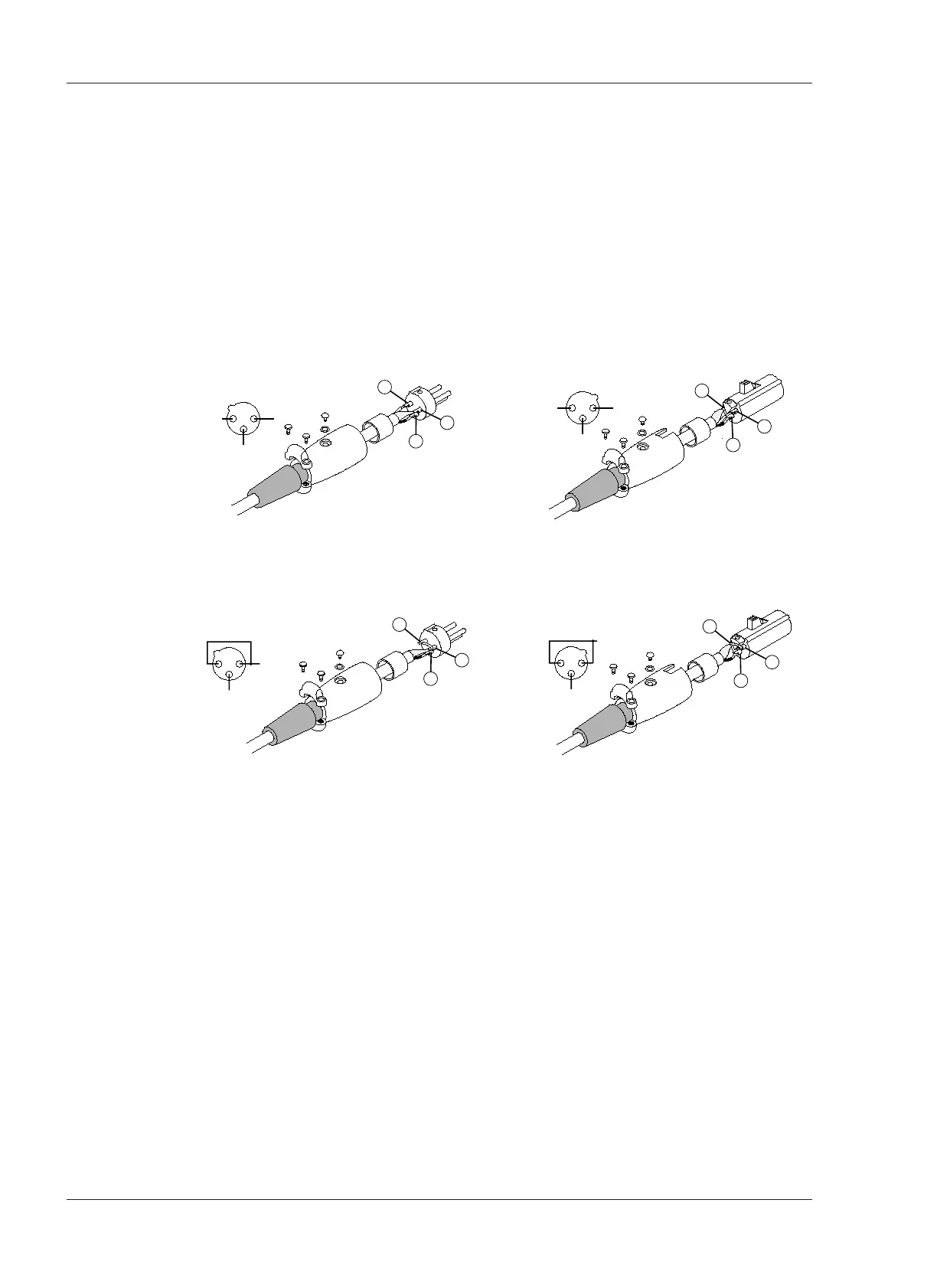
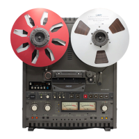
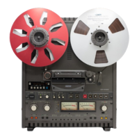
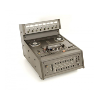
2.2.2 Balanced/Unbalanced Connection
The Input/Output connectors are balanced as shown in Figure 2-2. The pin
assignment of the connectors is as follows:
Pin 1: Shield (GND)
Pin 2: Cold
Pin 3: Hot.
When connecting an unbalanced machine to the MX-5050, change the pin
assignment as shown in Figure 2-2.
Optional Input (ZA-53T)/Output (ZA-53S) Transformers are available from
OTARI. For details contact OTARI or your nearest OTARI dealer.
Figure 2-2
Balanced/Unbalanced Connectors