MX-5050 Operation and Maintenance Manual
May 1992
Section 2 Installation
2 - 9
2.4 PCB Assembly Location
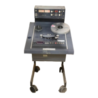
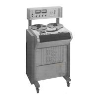
2.4.1 MX-5050 BIII
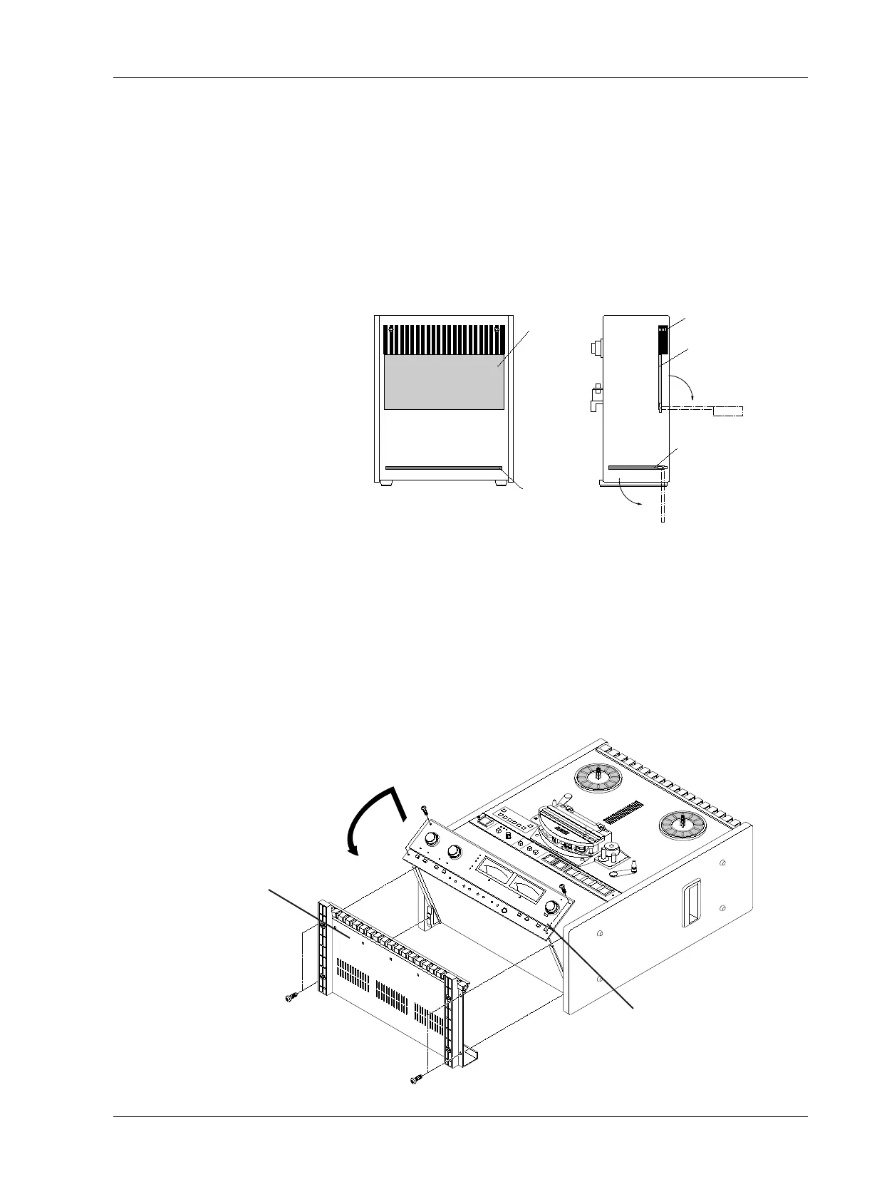
The PCB Assemblies are located as shown in Figure 2-5. The CONTROL PCB
Assembly is accessed by removing the rear panel. (Refer to Figure 2-9). The
CONTROL PCB can be rotated to adjust parts on the COMP side. To access
the REC/ REP AMP PCB Assembly, the AMP section of the MX-5050BIII must
be turned face up. The rotation of the AMP section is performed as follows.
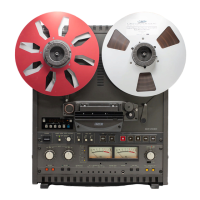
❏ AMP Section Rotation
1. Turn off the machine. Place the machine so that the transport faces upward.
Refer to Figure 2-6.
2. Remove the four screws holding the Bottom Cover. Remove the Bottom
Cover from the machine.
3. Remove the four screws holding the AMP section. While lifting the AMP
section slightly, rotate it to a horizontal position.