Section 6 Transport Adjustment and Parts Replacement
6 - 10
May 1992
MX-5050 Operation and Maintenance Manual
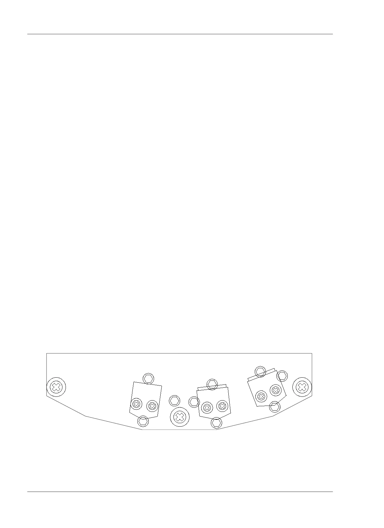
6.8 Head Assembly Replacement
The Head Assembly is mounted on the tape guide posts and is attached to
the Guide Posts with screws marked "M" (refer to Figure 6-9). Each Head
Stack is attached to the Head Bracket with screws marked "W", and the Head
Brackets are attached to the Head Base with the screws marked "H" "A" and
"T". These screws are used to adjust the position of the head.
When one of the head stacks needs to be replaced, use the following
procedure.
1. Raise the Head Cover
2. Remove the screws marked "M" and remove the head base from the tape
guides.
3. Unsolder the lead wires coming from the Head PCB.
4. Remove the Head Stack from the Head Base by removing screws "A", "T" and
"H".
5. Attach the new Head Stack to the Head Base with the screw removed in Step
4.
6. Resolder the wires removed in Step 3.
7. Mount the Head Base to the Tape Guides with the screws "M".
After replacement of the heads, perform Head Position adjustment § 6.9) and
Azimuth Adjustment (§ 7.3.1 and § 7.4.3)
In addition to the above adjustments, the following adjustments are
necessary.
Repro Head
B. Reproduce EQ Adjustment § 7.3.3
Record Head
A. Record Bias Adjustment § 7.4.1
B. Record Level Adjustment § 7.4.3
C. Record EQ Adjustment § 7.4.4