EasyManua.ls Logo

OTARI MX-5050 - Transport Control Panel

OTARI MX-5050
146 pages
Print Icon
To Next Page IconTo Next Page
To Previous Page IconTo Previous Page
Loading...
MX-5050 Operation and Maintenance Manual
May 1992
Section 3 Controls and Indicators
3 - 3
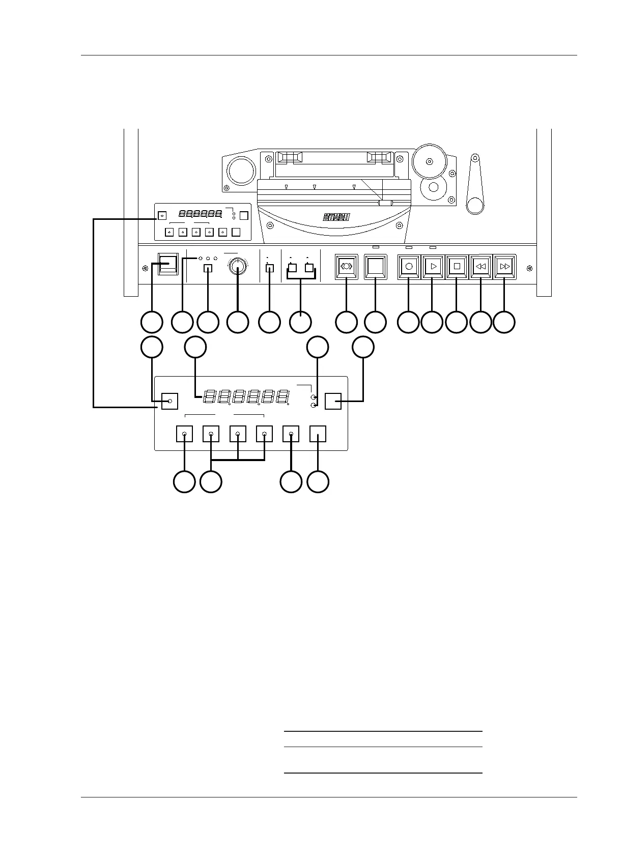
3.2 Transport Control Panel
Numbers in brackets [ ] refer to Figure 3-2.
[1] POWER Switch
Pressing the upper portion of the Switch turns on the machine.
[2] Tape Time Display
This 6-digit display shows the tape time in Hours, Minutes, and Seconds; the
tape speed in ips (inches per second); or the tape speed as a percentage
change from the selected play speed, as set by the TIME·IPS·% Button [5].
[3] SET Button
Pressing this button initiates Set mode, in a desired value can be entered by
using the SEARCH keys. There are two Set modes:
A. Cue Point Set mode: Refer to § 4.5.1
B. Vari Speed Set mode: Refer to § 4.4.6
[4] Tape Speed Indicator
This LED indicates the selected speed.
Hi Version Low Version (BIII-2)
Hi: 15 ips Hi: 7.5 ips
Low: 7.5 ips Low: 3.75 ips
EDIT
ON
OFF
SPEED MODE
EXT FIX VARI
PITCH CONTROL
POWER
DOWN
UP
SPEED
L
H
CUE
SET
ZERO 1 2 3 REPEAT CLR
TIME-IPS-%
SEARCH
HMS
H
L
TAPE SPEED
1 11 10 12 13 14 15 16 17 18 19 20 21
SET
ZERO 1 2 3 REPEAT CLR
TIME-IPS-%
SEARCH
HMS
H
L
TAPE SPEED
3 542
76 8 9
REEL SIZE
S
L
S
L
SUP T.UP
Figure 3-2
Transport Control Panel
1. POWER Switch
2. Tape Time Display
3. SET Button
4. Tape Speed Indicator
5. TIME·IPS·% Button
6. SEARCH ZERO Button
7. SEARCH 1, 2, 3 Buttons
8. REPEAT Button
9. CLR Button
10. Speed Mode Select
Button
11. Speed Mode Indicator
12. Pitch Control Knob
13. Tape Speed Select
Button
14. Reel Size Selector
Switch *
15. CUE Button
16. EDIT Button
17. RECORD Button
18.PLAY Button
19. STOP Button
20. REWIND Button
21. F.FWD Button

Table of Contents

Other manuals for OTARI MX-5050

Related product manuals