MX-5050 Operation and Maintenance Manual
May 1992
Section 2 Installation
2 - 13
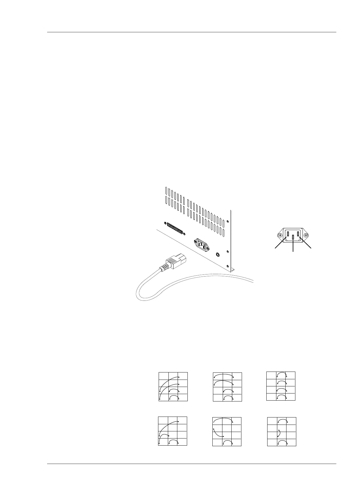
2.5 Power Connection
Confirm that the power voltage marked on the rear panel corresponds with
the line voltage being used.
❏ Turning on the machine
For power connection, use the included Power Cable. Connect the Power
Cable plug to the power connector located at the rear of the machine. Make
sure that the machine is turned off before connecting the other end of the
power cable to the AC line outlet. The machine is now ready to be turned on.
Pressing the upper portion of the POWER Switch applies power to the
machine. After power is applied to the machine, the VU meters, tape timer
digits, and the indicator above the STOP button will illuminate. The Tape
Timer will show the selected tape speed for several seconds after the
machine is turned on, and then will change to tape time indication.
Turning on the machine while pressing the STOP button will cause the ROM
version of the Control PCB Assembly to be displayed.
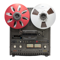
❏ AC Voltage Connector Replacement
When the AC Line Voltage is different from the factory setting, the Line
Voltage connector should be changed to the proper one. In this case, contact
OTARI or nearest OTARI dealer and order the proper Line Voltage connector.
The Line Voltage connector (white) is located beside the Supply Reel Motor.
First remove the rear panel and replace it. The following figure describes the
wiring of the connectors.