Section 7 Audio Alignment
7 - 4
May 1992
MX-5050 Operation and Maintenance Manual
7.2.2 Test Oscillator Waveform and Level Adjustment
Perform this adjustment after the Level Matching Adjustment (§ 7.2.1) has
been completed.
1. Set the Monitor button of CH1 to SOURCE position.
2. Press the 1kHz TEST OSC button on the AMP Panel.
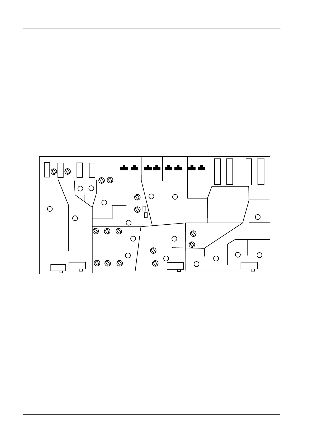
3. Adjust VR502 on the REC/REP AMP PCB Assembly (see Figure 7-1) so that
the VU meter indicates 0 VU. Perform the same adjustment to the CH2
REC/REP AMP PCB Assembly.
4. Press the 10kHz OSC FREQ button.
5. Adjust VR501 so that the VU meter indicates 0VU.
Switches and Trimmers on the REC/REP AMP PCB
Figure 7-1
REC/REP AMP PCB (DIP Side)
SW301 Record Selection L Ch
SW401 Record Selection R Ch
SW302 SEL/REP Selection LCh
SW 402 SEL/REP Selection R Ch
SW 506 TEST OSC 1kHz
SW507 TEST OSC 10kHz
SW102 Monitor Selection LCh
SW202 Monitor Selection R Ch
SW501 Mic. Attenuator
SW502 Record Level Selection
SW503 EQ(NAB/IEC) Selection
SW504 Output Level Selection
VR306 Bias L CH
VR406 Bias R CH
VR303 REC EQ High Speed L CH
VR304 REC EQ Low Speed L CH
VR403 REC EQ High Speed R CH
VR404 REC EQ Low Speed R CH
VR305 REC Level L CH
VR405 REC Level R CH
VR106 REP SRL Level LCH
VR206 REP SRL Level R CH
VR108 Input Level L CH
VR208 Input Level R CH
VR501 OSC Level (10kHz)
VR502 OSC Level (1kHz)
VR101 SEL-REP Level L CH
VR201 SEL-REP Level R CH
VR205 Low F Comp. R CH
SW201 Low Comp. Selection R Ch
VR105 Low F Comp. L CH
SW101 Low Comp. Selection L Ch
VR102 15ips REP EQ L CH
VR103 7.5ips REP EQ L CH
VR104 3.75ips REP EQ LCH
VR202 15ips REP EQ RCH
VR203 7.5ips REP EQ RCH
VR204 3.75ips REP EQ RCH