2.3 Switch Position Adjustment
If necessary, change the following switch settings on the rear panel before operating the
machine.
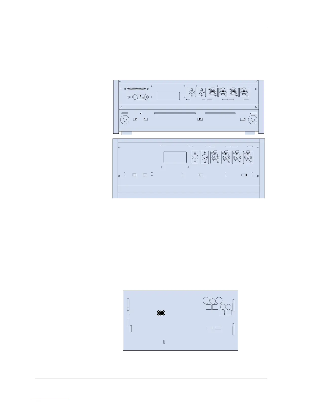
SW501: MIC. Attenuator (0 dB/-20 dB/OFF)
SW502: Ref. Flux H/M/L (320/250/185 nWb/m)
SW503: EQ Setting (NAB/IEC)
SW504: Output Level Setting (H = +4 dBu, L = -16 dBu)
Figure 2-3 Switches on Rear Panel (Above = BIII, Below = MKIV-2)
DIP Switch settings on the CONTROL PCB
NOTE: When any of the following DIP switch settings are changed, the machine must be
turned off and on for the settings to take effect.
SW1-1 Speed Version SW2-1 SEARCH 3 key Selection
SW1-2 Punch-In SW2-2 SEARCH 3 key Selection
SW1-3 Punch-Out SW2-3 Stop Mute Selection
SW1-4 Capstan PLL Reference SW2-4 Fast Wind Mute Selection
SW1-5 Capstan PLL Reference SW2-5 Play Start Mute
SW1-6 Punch-In Type Select SW2-6 Machine Type
SW1-7 REC LED Flashing Select SW2-7 Machine Type
SW1-8 External Control Select SW2-8 Not used
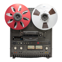
Refer to Figure 2-4 for the location of these DIP switches on the CONTROL PCB
Assembly.
Figure 2-4 Controls on the CONTROL PCB Assembly
MX-5050mkIV-2/BIII-2 Operation and Maintenance Manual
6 1999-02