2.2 Audio Signal Connection
2.2.1 Audio Connectors
The input to the machine is transformerless and balanced with an input impedance of 10
k. The input level is fixed to +4 dBu.
The output from the machine is transformerless and balanced. The nominal output level is
selected from +4 dBu or -16 dBu with the switch on the rear panel. The output level is set
to +4 dBu at the factory.
The microphone input-is balanced with an input impedance of 10 k. Input level can be
attenuated by 20 dB with the attenuation switch on the rear panel.
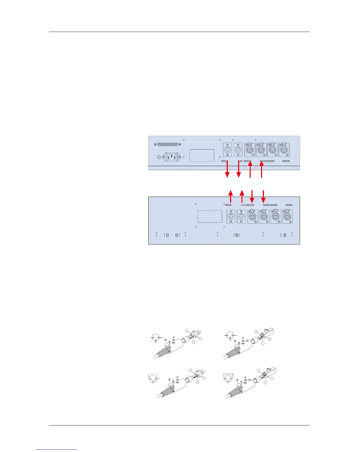
The connections to the Input/Output connectors are as shown in Figure 2-1.
PARALLEL I/O
GROUND POWER
LINE INPUTLINE OUTPUT
CH2CH1 CH1CH2CH1
CH2
MIC INPUT
Output Input
LINE INPUTLINE OUTPUT
CH2CH1 CH1CH2CH1
CH2
MIC INPUT
MIC ATTENUATOR
0dB -20dB OFF
REF FLUX
LOW MID HIGH
EQUALIZATION
IEC NAB
OUTPUT LEVEL
LOW HIGH
Output
Input
Figure 2-1 Input/Output Connectors (Above = BIII, below = MKIV-2)
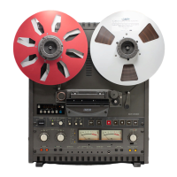
2.2.2 Balanced/Unbalanced Connection
The Input/Output connectors are balanced as shown in Figure 2-2. The pin assignment of
the connectors is as follows: Pin 1 = Shield (GND), Pin 2 = Cold, Pin 3 = Hot.
When connecting an unbalanced machine to the MX-5050, change the pin assignment as
shown in Figure 2-2.
Optional Input (ZA-53T)/Output (ZA-53S) Transformers are available from Otari. For details
contact Otari or your nearest Otari dealer.
2
1 GND
3
HOT
COLD
2 1
GND
3
HOT
(SHIELD)
COLD
2
3
1
1
2
3
Balanced Input
Balanced Output
HOT
2
1 GND
3
2
1
3
HOT
GND
2
1
3
3
1
2
Unbalanced Input
Unbalanced Output
Figure 2-2 Balanced/Unbalanced Connectors
MX-5050mkIV-2/BIII-2 Operation and Maintenance Manual
1999-02 5