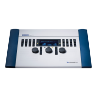
Connection panel - MADSEN Astera²
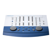
The connections are located at the back of MADSEN Astera².
All four cables for connecting accessories are joined in a bundle and color-coded for easy connection:
• Yellow: Operator desktop microphone
• Green: Operator monitor headset, headphones
• Pink: Operator monitor headset, boom microphone
• Gray: Operator monitor speaker
A. Patient Responders
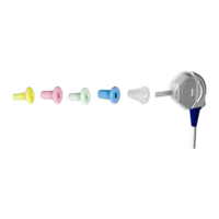
B. Insert earphones
C. Headphones - air conduction
D. High-frequency headphones - air conduction
E. Bone oscillator
F. Operator monitor headset - headphones
G. Operator monitor headset - boom microphone
H. Operator monitor speaker
I. Operator desktop microphone
J. Talkback microphone
K. Assistant monitor headset
L. Sound field speakers (power output)
M. External power supply
N. PC/USB connection
O. Line-in
P. Sound field speakers (line output)
Note • Blue corresponds to Left and red corresponds to Right.
Warning• Use only the power supply provided by Otometrics.
Caution• When you connect other electrical equipment to MADSEN Astera², remember that equipment that does not
comply with the same safety standards as MADSEN Astera² can lead to a general reduction in the system's safety
level.
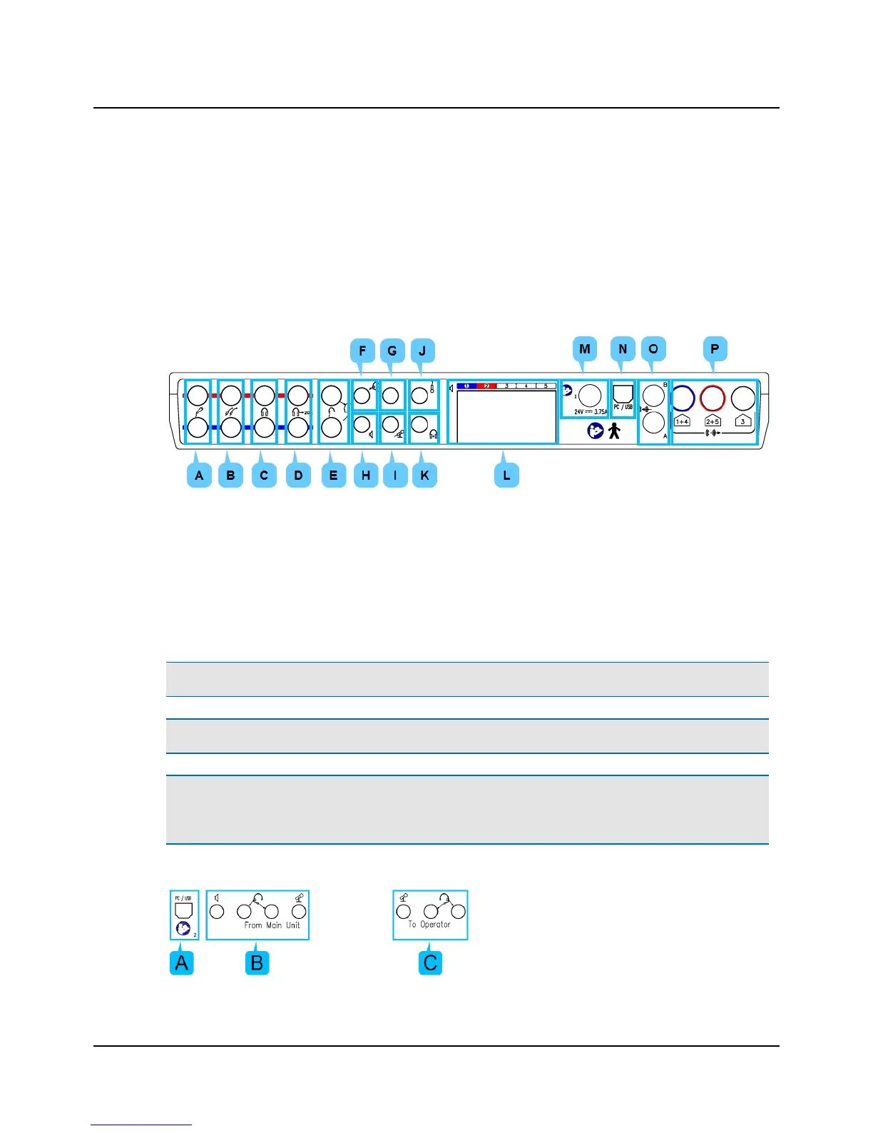
Connection panel - ACP
10 Otometrics - MADSEN Astera²
4 Installation