a) Removing/installing one of the following interface adapters:
• Trapezoid adapter
• Parallel adapter
• "Dräger" type
• Leckey "Squiggles", "Mygo", "Mygo Max", "KIT seat" types
1) Remove the seating shell / seating system with the seating shell interface.
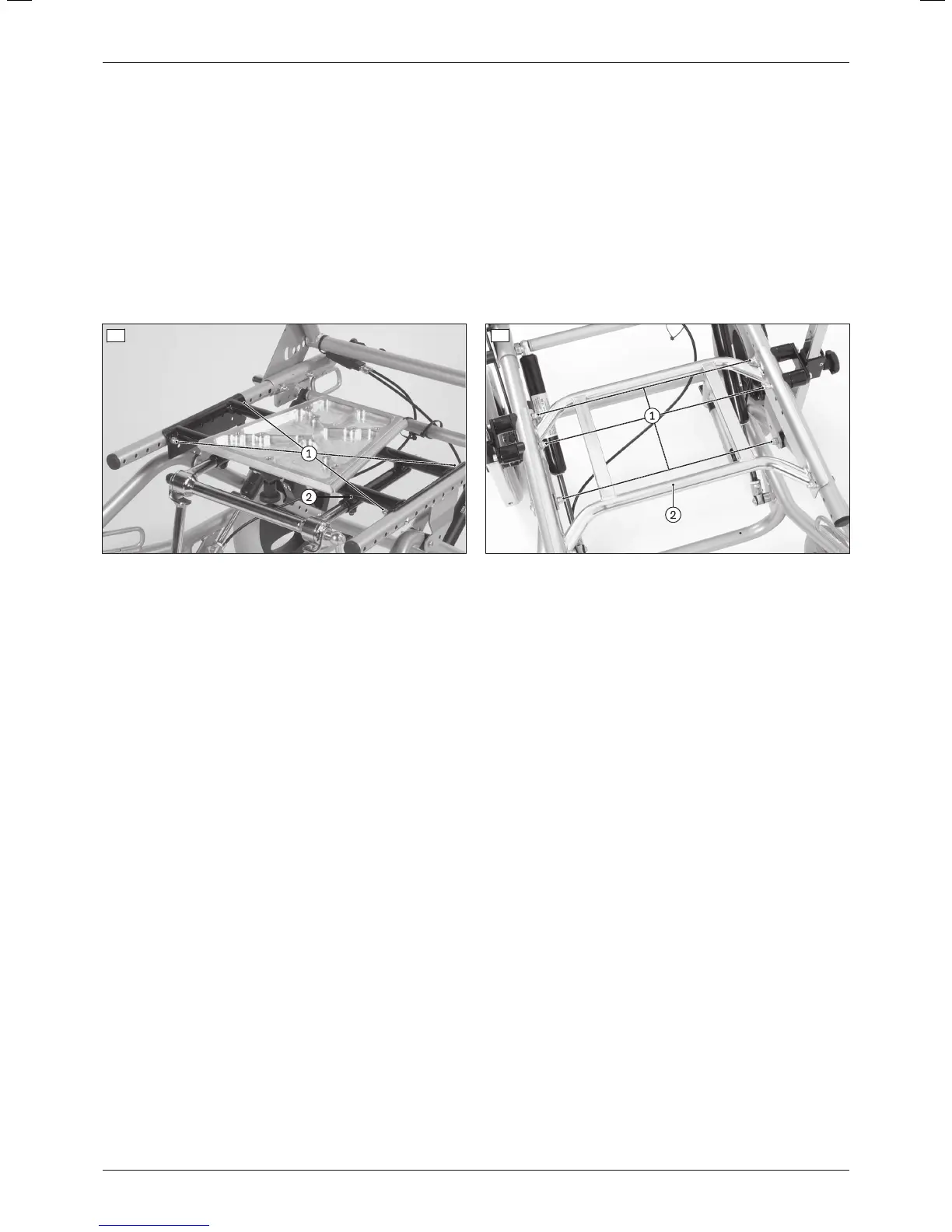
2) Loosen and remove the screw connections between the interface adapter and seat bars (see fig.4, item1; see
fig.5, item1).
3) Remove/replace the interface adapter (see fig.4, item2; see fig.5, item2).
4) Insert the screw connections into the appropriate slots between the interface adapter and seat bars and firmly
tighten them to a torque of 10Nm (see fig.4, item1; see fig.5, item1).
5) Remount the seating shell / seating system with the seating shell interface.
4 5
b) Removing/installing one of the following interface adapters:
• Universal adapter (crossbars)
• "Shape/Moss" type
1) Remove the seating shell / seating system with the seating shell interface.
2) Loosen and remove the screw connections between the backrest attachment device and the seat bar on both
sides (see fig.6, item1).
CAUTION! Risk of pinching between freely movable frame components. Actively secure the back
frame and the seat frame against falling.
INFORMATION: Mark / take note of the original seat depth and position of the backrest attachment
devices.
3) Loosen and remove the screw connection between the perforated plate and gas compression spring on both
sides (see fig.7, item1).
CAUTION! Risk of pinching between freely movable gas compression springs. Actively secure the gas
compression springs against falling.
4) Slide the backrest attachment devices down and off the seat bars and set them safely aside with the back
frame (see fig.6, item2).
5) Loosen and remove the screw connections between the interface adapter and seat bars.
6) Slide the interface adapter down and off the seat bars / replace it.
7) Insert the screw connections between the interface adapter and seat bars and firmly tighten them to a torque of
10Nm.
8) Slide the back frame together with the backrest attachment devices onto the seat bars (see fig.6, item2).
INFORMATION: Return the backrest attachment devices and the gas compression springs to their ori
ginal position.
9) Reinsert all screw connections in their original positions and firmly tighten them to a torque of 10Nm (see
fig.6, item1; see fig.7, item2).
10) Remount the seating shell / seating system with the seating shell interface.
13Discovery
Settings