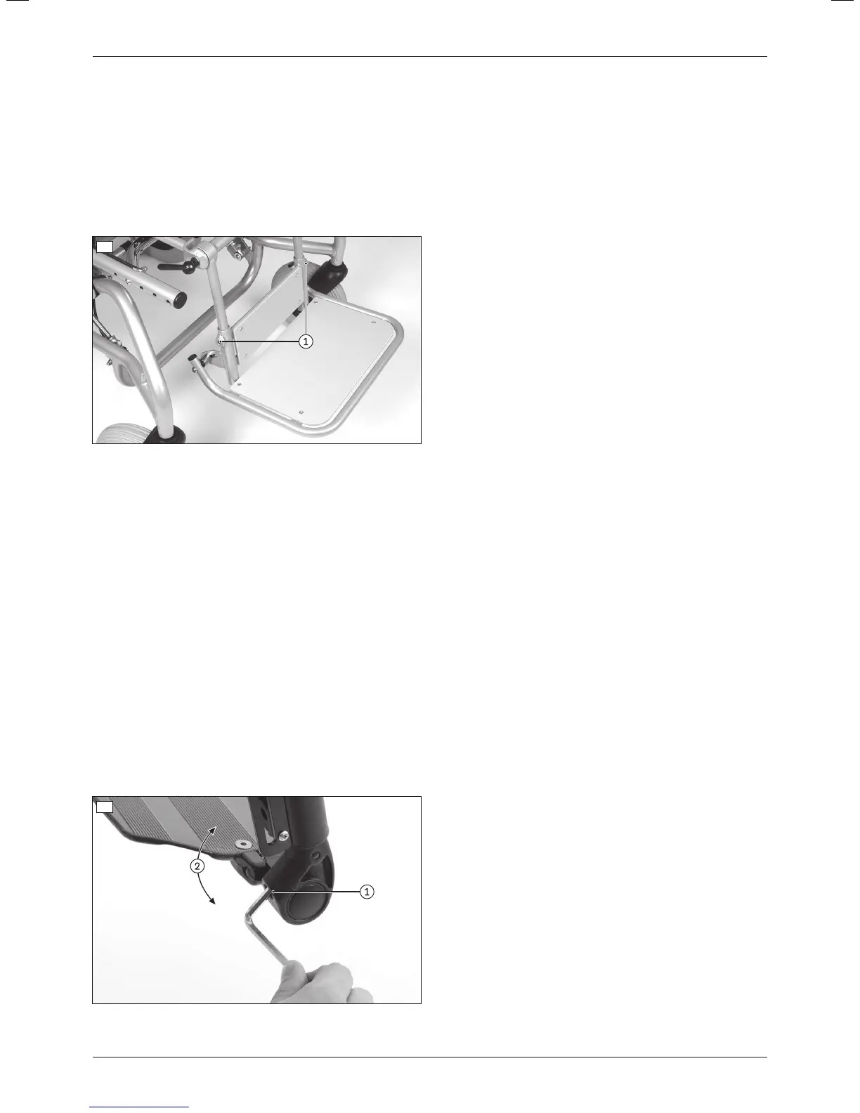
b) Adjusting the lower leg length of the following legrests:
• With single-panel footplate for seating shell interface (steel)
1) Loosen the clamping screws on both mounting bars (see fig.28, item1).
2) Adjust the lower leg length (continuously adjustable). The guide tubes for the footplate must remain slid onto
the mounting bars of the legrest by at least 40mm, as they could otherwise slide down and off the mounting
bars.
INFORMATION: Verify sufficient ground clearance.
3) Firmly tighten the clamping screws on both mounting bars to a torque of 1.5Nm (see fig.28, item1).
4) Check that the legrest is securely mounted.
28
6.9.3 Adjusting the support angle
The footplate angle setting should be chosen so that the ankle is in a relaxed, comfortable position.
a) Adjusting the support angle of the following legrests:
• Segmented (aluminium)
• Segmented for short lower leg length (aluminium)
• Elevating with ratchet joint (aluminium)
1) Loosen the clamping screw on the joint of the footplate (see fig.29, item1).
2) Set the desired footplate angle (see fig.29, item2).
3) Firmly tighten the clamping screw on the joint of the footplate to a torque of 10Nm (see fig.29, item1).
b) Adjusting the support angle of the following legrest:
• Single-panel
1) Loosen the clamping screw on the left and right joint of the footplate (see fig.29, item1).
2) Set the desired footplate angle (see fig.29).
INFORMATION: Set the same angle on the left and right joint so that the footplate is correctly posi
tioned.
3) Firmly tighten the clamping screw on the left and right joint of the footplate to a torque of 10Nm (see fig.29,
item1).
29
21Discovery
Settings