CAUTION
Incorrectly adjusted anti-tipper
Tipping over, falling, loss of functionality due to incorrect adjustment
► After it is adjusted, the anti-tipper always has to protrude a few centimetres beyond the outer radius of the rear
wheel.
► The adjustments must always be done in the same way on both sides.
► After making adjustments, take note of the sound made by the anti-tipper locking mechanism as it engages.
► After making any adjustments to the product, verify the proper functionality of the anti-tipper. Adjust the anti-
tipper if needed.
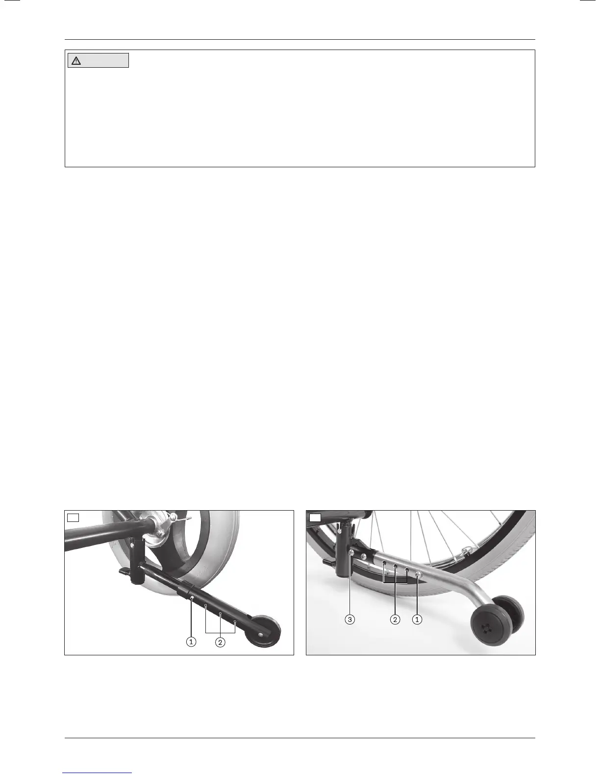
6.15.2.1 Adjustment for 12" rear wheels
With this version, the length/height of the anti-tipper can only be adjusted in one operation.
1) Push in the tripod spring on the bar of the anti-tipper (see fig.46, item1).
2) Adjust the length/height of the anti-tipper using the perforated holes (see fig.46, item2).
INFORMATION: The anti-tippers must be no more than 50mm above the floor.
INFORMATION: After making this adjustment, the anti-tipper has to protrude a few centimetres bey
ond the outer radius of the rear wheel.
3) Allow the tripod spring to engage.
4) Check the height of the anti-tipper and readjust it if necessary.
6.15.2.2 Adjustment for 22"/24" drive wheels (custom fabrication version)
With this version, the length and height of the anti-tipper can be adjusted separately.
Adjusting the length of the anti-tipper
1) Loosen and remove the screw connection on the bar of the anti-tipper (see fig.47, item1).
2) Adjust the length of the anti-tipper using the perforated holes (see fig.47, item2).
INFORMATION: After making this adjustment, the anti-tipper has to protrude a few centimetres bey
ond the outer radius of the rear wheel.
3) Insert the screw connection into the appropriate hole on the bar of the anti-tipper and firmly tighten it (see
fig.47, item1).
4) Check the height of the anti-tipper and adjust it if necessary.
INFORMATION: The anti-tippers must be no more than 50mm above the floor.
Adjusting the height of the anti-tipper
1) Loosen and remove the screw connection on the joint of the anti-tipper (see fig.47, item3).
2) Adjust the height of the anti-tipper.
INFORMATION: The anti-tippers must be no more than 50mm above the floor.
3) Insert the screw connection into the appropriate hole on the joint of the anti-tipper and firmly tighten it (see
fig.47, item3).
46 47
7 Delivery
7.1 Final inspection
A final check must be carried out before the wheelchair can be handed over:
29Discovery
Delivery