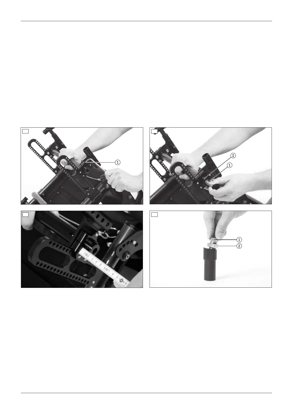
3) Loosen the clamping screw on the clamping flange (see fig.13, item1).
INFORMATION: The adjustment must be made on one side first and then on the other.
INFORMATION: The track width must be adjusted symmetrically on both sides.
4) Insert the rear wheel's quick-release axle into the camber module to aid removal (see fig.14, item1).
5) Move the camber module (see fig.14, item2) to the desired position outwards with the aid of the quick-release
axle or inwards with the help of a soft-faced hammer.
→ Do not pull the camber module out too far. During installation the whole camber module must be fully
enclosed by the clamp bracket.
→ Check the position by measuring it afterwards (see fig.15).
6) Clamp the camber module lightly using the clamping screw on the clamping flange.
7) Adjust the track width in the same fashion on the other clamping flange. Make sure that both camber modules
have been adjusted symmetrically.
8) Attach the wheels.
9) Make the track adjustments (see Page14).
10) Tighten the clamping screws to 10Nm (see fig.13, item1).
13 14
15 16
Adjusting camber module 6°/9°
1) Remove the wheels.
2) Place the wheelchair upside down.
3) Loosen the counter nut on the fitting (see fig.16, item2).
4) Set the desired track width with the fitting (see fig.16, item1). If required, put on the wheel to check that it can
rotate freely.
INFORMATION: The track width must be adjusted symmetrically on both sides.
5) Slightly tighten the counter nut on the fitting.
6) Adjust the track width in the same fashion on the other camber module.
7) Attach the wheels.
8) Make the track adjustments (see Page14).
9) Tighten the counter nut to 50Nm (see fig.16, item2).
13Ventus
Settings
 Loading...