Outlaw Audio
8
Before you connect any audio or video components to the
Model 975, it’s important to understand how the dier-
ent buttons, switches, and connections work. Most A/V
source devices now oer several connection options, and
unless you choose the proper ones, you won’t get the best
possible audio and video quality. The following two sec-
tions oer a brief explanation of the front and rear panel
components of the Model 975.
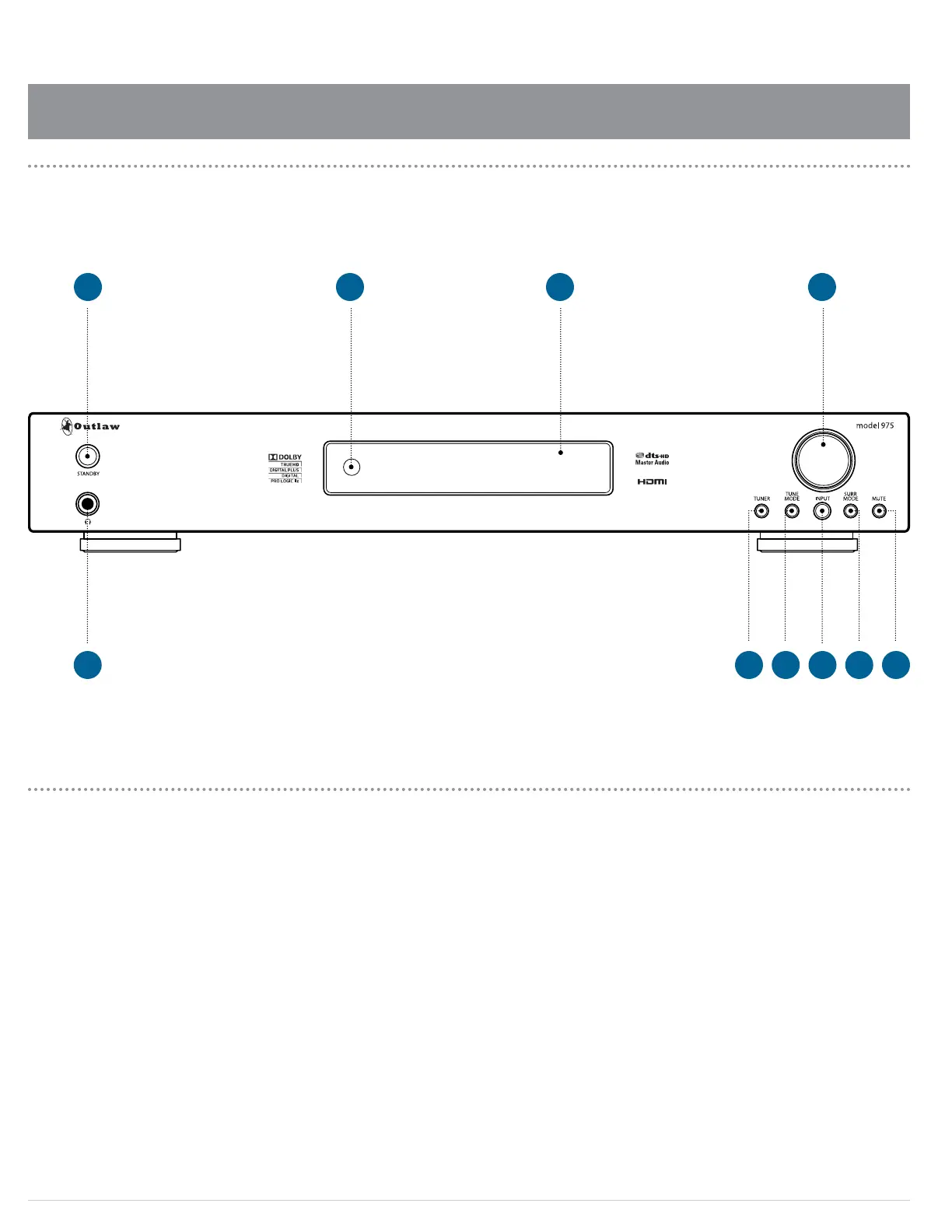
A. STANDBY power button (see page 37)
Pressing this button turns the unit on and o. When
the unit is on, the blue ring around the button glows
brightly and the front panel display illuminates.
When the unit is o, the blue ring glows dimly, the
front panel display turns o, control functions are
disabled, and all outputs are muted.
B. IR sensor
The IR sensor receives commands from the remote
control. Do not block or cover it. If the unit is inside a
cabinet or behind tinted glass doors you may need to
use an optional external IR sensor.
C. Front panel display (see page 15)
Indicates program source, DSP mode, channel inputs,
tuner preset and/or frequency, digital input, volume
level, and other preamp/processor/tuner operating
information. Display is not dimmable.
D. VOLUME control (see page 38)
Adjusts the volume level for the line outputs and the
headphone jack.
E. Headphone jack (see page 43)
This jack can be used with stereo headphones that
have a standard 1/4-inch plug. Headphones with
a miniature 1/8-inch/3.5mm plug (the type found
on smartphones and MP3 players) can also be used
with an adapter, available at most electronics stores.
Inserting a 1/4-inch headphone plug mutes the other
outputs. The VOLUME control adjusts listening level.
F. TUNER button (see page 44)
This button selects the radio tuner. The front panel
display will show which band (AM or FM) is active, and
the frequency of the station currently tuned. Pushing
the button again will toggle between AM and FM.
G. TUNE MODE button (see page 46)
Toggles between stereo and mono FM tuning modes
when the tuner is selected source and the FM band is
selected. Does not operate when AM is selected.
H. INPUT button (see page 37)
Pushing this button repeatedly cycles among the ve
input sources (TV, Disc, Game, Vid, and Aux) and the
AM/FM tuner.
I. SURR MODE button (see page 39)
Press this button repeatedly to activate the matrix
surround sound modes and choose among the various
surround modes provided by the Model 975. The
available surround modes will depend on whether you
are listening to a 2-channel, 5.1 or 7.1 signal, and what
loudspeaker conguration you are using.
J. MUTE button (see page 38)
This button mutes the line and headphone outputs.
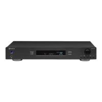
Model 975 Front Panel
Model 975
Front Panel controls
F H JIG
A B C D
E
 Loading...