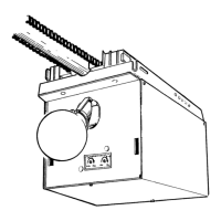
Fig. 1-4
Adjusting
Bolt
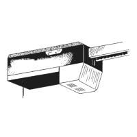
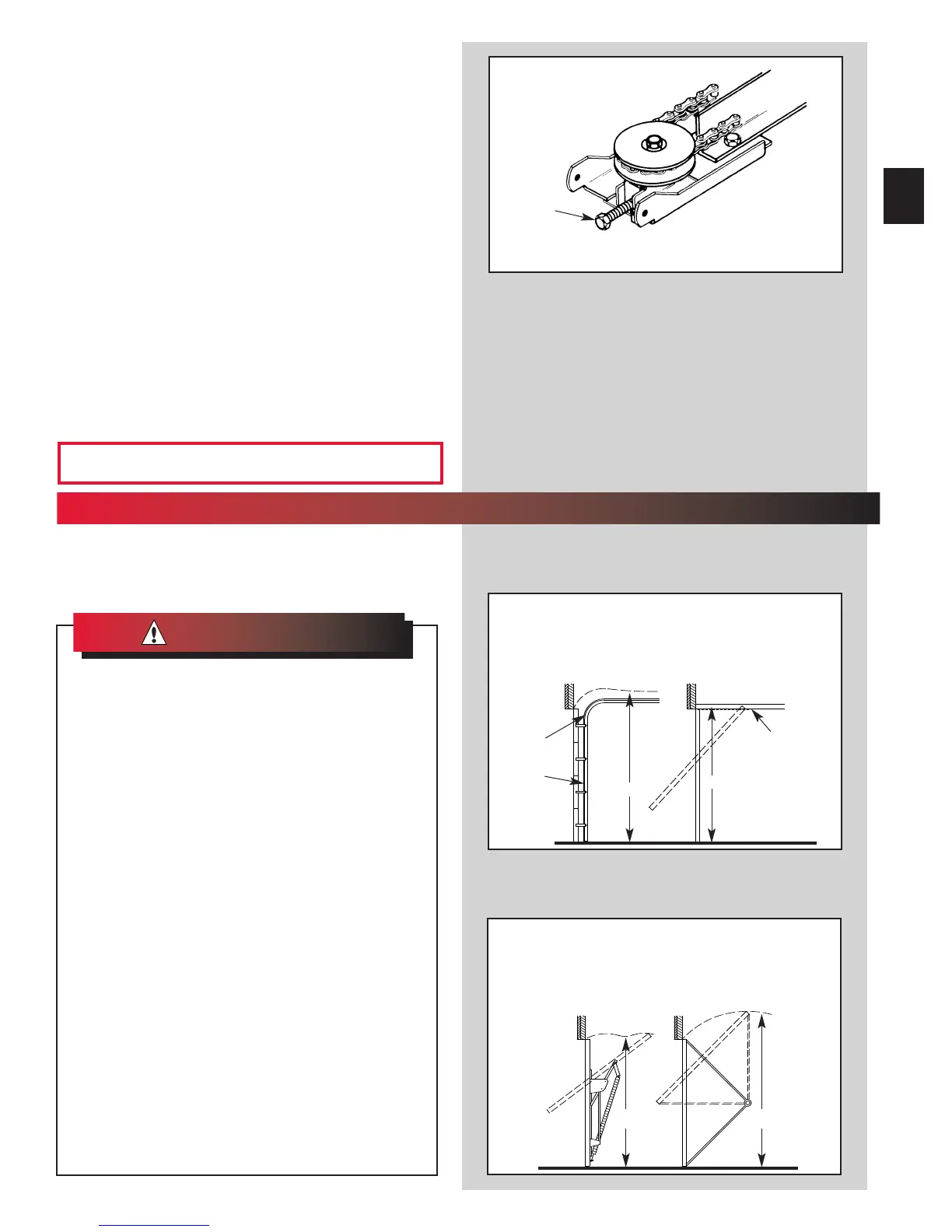
WHAT TYPE OF DOOR DO YOU HAVE?
Look at the drawings below. They tell you where to find
the installation instructions you need
Track Guided Doors
SEE SECTION 2A
Trackless Doors
SEE SECTION 2B.
Section Door With
Curved Track Hardware
1-Piece Door With
Horizontal Track Hardware
Curved
T
rack
with
Vertical
Section
Straight Track
(Horizontal Only)
1-Piece Door
Jamb Type Hardware
(No Track)
1-Piece Door
Pivot Type Hardware
(No Track)
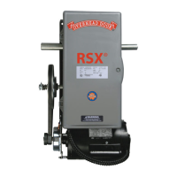
5. Fasten rail to power head.
• Align mounting holes of sprocket saddle, rail
and p
ower head frame.
• Insert the two (2) 5/16” x 1/2” hex head
scr
ews[112], then two (2) No. 10-24 x 1/2” hex
head scr
ews [69].
• Tighten screws.
NOTE: Inner-slide/bullet should remain at mid-travel
when assembling t
o power head to provide proper
travel when setting limits.
6. Use adjusting bolt to set chain tension (Fig. 1-4)
• Chain should sag slightly but not so much that it
dr
ags on the rail.
“H”
“H”
“H”
DOTTED LINE AT “H”
INDICATES HIGHEST
POINT OF TRA
VEL
“H”
2
...
INSTALLATION
FOR HELP—1-800-929.3667 OR OVERHEADDOOR.COM
11
WARNING
:
IMPORTANT
INSTALLATION
INSTRUCTIONS
1. READ AND FOLLOW ALL SAFETY, INSTALLATION AND
OPERATION INSTRUCTIONS. If you have any questions or
do not understand an instruction, call your service
representative.
2. Do Not install operator on an improperly balanced door. An
improperly balanced door could cause severe injury.
Repairs and adjustments to cables, spring
assembly, and other hardware must
be made by a trained service person using
proper tools and instructions.
3. Remove all ropes and disable all locks connected to the
door before installing operator.
4. Install door operator 7 feet or more above the floor. Mount
the emergency release knob 6 feet above the floor.
5. Do Not connect the operator to the source of power until
instructed to do so.
6. Locate the control button:
• Within sight of door.
• At a minimum height of 5 feet, so small children cannot
reach it.
• Away from all moving parts of the door.
7. Install the entrapment WARNING label next to the wall but-
ton or console. Install the emergency release tag on, or
next to, the emergency release.
8. The operator must reverse when the door contacts a 1-1/2
inch high object on the floor at the center of the doorway.
This is about the size of a 2” x 4” board laid flat.
To reduce the risk of
severe injury or death:
WARNING
:
OPEN ORANGE PARTS BAG

 Loading...