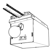
Fig. 1-3
No. 10-24 x 1/2” Hex Head Screws
5/16” x 1/2” Hex Head Screws
“D” -Shaft and Hole
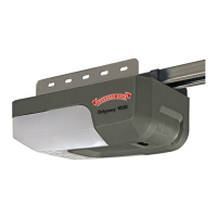
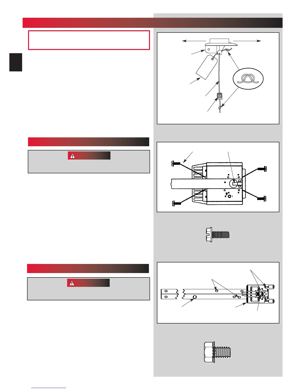
3. Place power head and channel on clean,flat surface.
4. Slide drive end of channel down over “D”-shaft on top of
p
ower head (Fig.1-2).
• Support header end of channel level with power head.
• Slide carr
iage to align “D”-shaft with “D”-hole in sprocket.
• Slide channel down “D”-shaft flush with power head.
5. Fasten channel to power head .
• Align mounting holes in front and r
ear of power head frame.
• Insert and securely tighten the four (4) No. 10 x 1/2”hex
head screw
s
[
69
]
.
NOTE: Chain inner-slide or belt bullet should remain at mid-
tra
vel when assembling to power head to provide proper travel
when setting limits.
1.
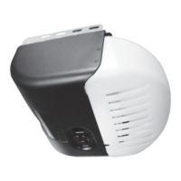
Attach emergency release knob cord (Fig. 1-1).
• Tie overhand knot in end of cord.
• Thread cord through knob so knot is inside knob.
• Thread cord through hole in carriage lever.
• Tie overhand knot in other end of cord.
Do Not cut cord until after power head is mounted.
2. Attach emergency release tag (Fig. 1-1).
• Thread wire through hole in carriage lever.
• Wrap wire around itself, tie securely.
PLEASE NOTE THE ASSEMBLY PROCEDURES ARE
DIFFERENT FOR RAIL AND CHANNEL. BE SURE TO
FOLLOW THE APPLICABLE STEPS.
Fig. 1-2
Fig. 1-1
Do Not attempt to run power head or to set limits until
operator is fully assembled and attached to the door.
“D” -Shaft and Hole
Hex Head Screws
Carriage Stop
CAUTION
Do Not attempt to run power head or to set limits until
operator is fully assembled and attached to the door.
Toward Door Toward Power Head
Carriage
No. 10 x 1/2” Hex Head Screw
5/16” x 1/2” Hex Head Washer Screw
Emergency
Release
Tag
Emergency
Release
Cord
Emergency
Release
Knob
Sprocket Saddle
1
...
OPERATOR ASSEMBLY
FOR HELP—1-800-929.3667 OR OVERHEADDOOR.COM
10
CHANNEL & POWER HEAD ASSEMBLY
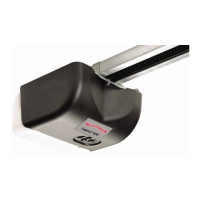
RAIL & POWER HEAD ASSEMBLY
3. Place power head and rail on clean, flat surface.
4. Slide drive end of rail down over “D”-shaft on top
of power head (F
ig. 1-3).
• Support header end of r
ail level with power head.
• Slide car
riage enough to align “D”-shaft with “D”-hole
in sprocket.
• Slide rail down “D”-shaft flush with power head.
dr
ags on the rail
CAUTION
OPEN BLUE PARTS BAG
Screws for attaching light cover are included in this bag.
Please set aside for use later.
[
69
]
[
112
]
[
69
]
[
69
]
[
112
]

 Loading...