NEC
CLASS 2
1
2
3
4
5
6
MORE
FORCE
PUSH
BUTTON
SAFETY
BEAM
LIMIT
SET
OPEN
FORCE
CLOSE
FORCE
RADIO
SIGNAL
LEARN
CODE
COM
D
O NOT
PUSH
LIMIT SET
U
NLESS
DOOR IS
ATTACHED
NOTE:
USE ONLY WITH
SERIES II CONTROLS
CLOSE
MORE
OPEN
MORE
CLOSE OPEN
LIMIT ADJUSTMENT
U.S. Patent No. 5,243,784
5,221,869
WARNING
CONTACT REVERSE
Fine adjustments for limit switches (see Section 8) MUST
BE completed before starting CONTACT REVERSE.
• Open door, use wall con-
tr
ol. • Place a 2 by 4 board laid flat in center of
do
orway. • Close door.
• Door MUST stop and rev
erse to open position. If
it does not, repeat fine adjustments for down limit
switch and “CLOSE FORCE” adjustment until the
door will reverse to the open position.
NOTE: Set minimum force required to make door close.
If door does not reverse, decrease “CLOSE FORCE” until door
reverses.
During the following steps, the motor protector may
op
en. Wait about 20 minutes for protector to reset.
NOTE:
Use wall control to run door to the fully CLOSED
position before starting “OPEN FORCE” adjustment.
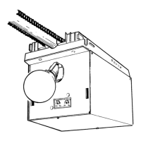
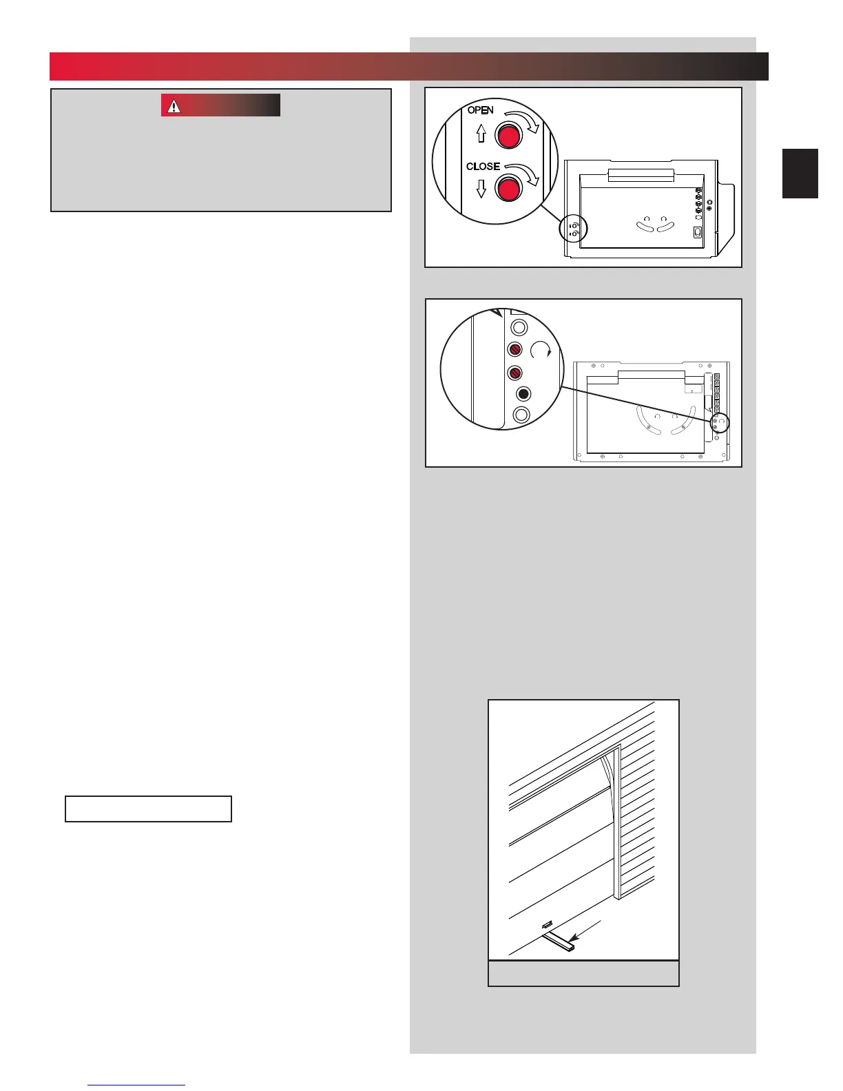
1. Adjust the “OPEN” Force (Fig. 7-1).
• Locate screw on back of power head marked
“OPEN FORCE.”
• Gently turn screw counterclockwise until it stops.
NOTE: Little effort is required to turn adjusting screw.
• Operate door using wall control.
• If door does not completely open, turn “OPEN
FOR
CE” screw clockwise slightly.
• Activate door using wall control.
• Repeat force adjustment until door will
c
ompletely open.
NOTE: Set minimum force required to make door open.
• Close door, use wall control.
2. Adjust the “CLOSE FORCE” (Fig. 7-1).
Use wall
control to run door to the fully OPEN position
before starting “CLOSE FORCE” adjustment.
• Locate screw on back of power head marked
“CLOSE FORCE.”
• Gently turn screw counterclockwise until it stops.
NOTE: Little effort is required to turn adjusting screw.
• Operate door using wall control.
• If door does not completely close, turn “CLOSE
FORCE” screw clo
ckwise slightly.
• Operate door using wall control.
• Repeat force adjustment until door will
c
ompletely close.
NOTE: Set the minimum forc
e required to make the door
close. Smaller the number the smaller the force.
3. (Fig. 7-2)
A
djust your door operator so that minimum force is
needed to operate door.
Position ladder to the side of the power head so that
it is clear of all moving parts of the power head, rail
assembly and door.
Fig. 7-2
1 1/2” Object
(or a 2 x 4
laid flat)
CONTACT REVERSE
Fig. 7-1
MORE MORE
LIMIT ADJUSTMENT
C
LOSE
O
PEN
P
USH
L
IMITS
T
O SET
4
3
2
1
CLASS 2
NEC
OPEN
CLOSE
O
PEN
CLOSE
MORE MORE
L
IMIT ADJUSTMENT
CLOSE
OPEN
PUSH
LIMITS
TO SET
4
3
2
1
CLASS 2
NEC
OPEN
CLOSE
O
PEN
C
LOSE
OR
N
EC
CLASS 2
1
2
3
4
5
6
MORE
FORCE
PUSH
BUTTON
SAFETY
BEAM
LIMIT
SET
OPEN
FORCE
CLOSE
FORCE
RADIO
SIGNAL
L
EARN
C
ODE
COM
DO NOT
P
USH
LIMIT SET
U
NLESS
D
OOR IS
ATTACHED
NOTE:
USE ONLY WITH
SERIES II CONTROLS
CLOSE
MORE
OPEN
MORE
CLOSE OPEN
LIMIT ADJUSTMENT
U.S. Patent No. 5,243,784
5,221,869
PRO MAX
STEALTH
7
...
FORCE ADJUSTMENT
FOR HELP—1-800-929.3667 OR OVERHEADDOOR.COM
23
 Loading...