CAUTION
WARNING
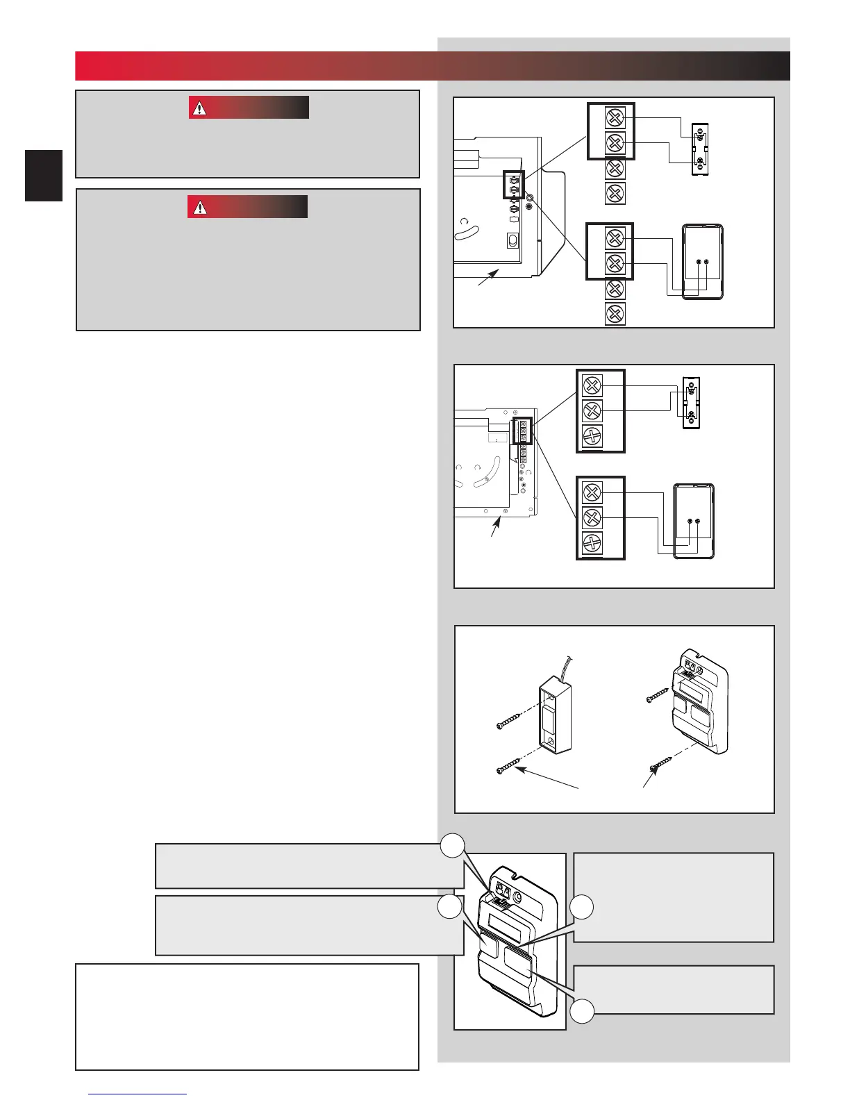
Wall console
Wall button
OR
Fig. 4-2
#6 x 1-1/4”
phillips pan head screws
Fig. 4-3
NOTE: Additional wall controls are available from your
dealer. ONLY ONE WALL CONTROL MAY BE THE LIGHTED
TYPE. If you have a lighted wall control, all of your addi-
tional wall controls must be un-lighted. More than one
lighted wall control will cause a malfunction.
1
2
3
4
MORE MORE
LIMIT ADJUSTMENT
CLOSE
OPEN
PUSH
LIMITS
TO SET
G4
Y3
B
2
W
1
MORE MORE
LIMIT ADJUSTMENT
CLOSE
O
PEN
PUSH
LIMITS
TO SET
G4
Y3
B2
W1
1. Run wire from power head to wall control.
• Place the wall control:
– In sight of door.
– At least 5 feet from floor, so small children can
not r
each it.
– Away from moving parts of door and
door hardware.
• Use staples to fasten wire to ceiling and wall.
2. Remove 1/2” insulation from each wire
(F
ig. 3-6)(pg. 19).
3. Attach wir
es to terminals (Stealth Fig. 4-1a)
(MAX Fig. 4-1b).
• Loosen, but Do Not remove screw from terminal.
For Stealth.
– Connect striped wires to terminal “2” on power
head and “B” on wall control.
– Connect white wire to terminal “1” on power
head and “W” on wall control.
For MAX.
– Connect strip
ed wires to terminal “1” on power
head and “B” on wall control.
– Connect white wire to terminal “2” on power
head and “W” on wall control.
4. Moun
t wall control (Fig. 4-2).
• For wall button and wall console, use two pan
head screws.
5. Mount entrapment warning label.
• Remove protective backing and stick near
w
all control.
• Use tacks or staples to permanently mount Label.
•
Make sure everyone reads and followsWARNINGS.
Power cord must be unplugged before attaching
wires. Be sure wire ends do not touch each other or
other terminals.
• Use of any other wall control will cause the
ligh
t not to work and could cause door to
operate by surprise.
• Cut or pinched wires can cause door operator
t
o malfunction. Drive staples just tight enough
to hold wire.
Fig. 4-1a
White
Striped
Wall
console
terminals
Wall
button
terminals
Power head
terminals
Back view
Back view
White
Striped
OR
Power
head
terminals
Rear view of
power head
Fig. 4-1b
NEC
C
LASS 2
1
2
3
4
5
6
MORE
FORCE
PUSH
BUTTON
SAFETY
BEAM
LIMIT
SET
OPEN
FORCE
CLOSE
FORCE
RADIO
SIGNAL
LEARN
CODE
COM
DO NOT
PUSH
LIMIT SET
UNLESS
DOOR IS
ATTACHED
NOTE:
U
SE ONLY WITH
S
ERIES II CONTROLS
CLOSE
MORE
OPEN
MORE
CLOSE OPEN
LIMIT ADJUSTMENT
U.S. Patent No. 5,243,784
5,221,869
NEC
CLASS 2
1
2
3
4
5
6
MORE
FORCE
PUSH
BUTTON
SAFETY
BEAM
LIMIT
SET
OPEN
FORCE
CLOSE
FORCE
RADIO
SIGNAL
LEARN
CODE
COM
D
O NOT
PUSH
LIMIT SET
UNLESS
DOOR IS
ATTACHED
NOTE:
U
SE ONLY WITH
S
ERIES II CONTROLS
CLOSE
MORE
OPEN
MORE
CLOSE OPEN
LIMIT ADJUSTMENT
U.S. Patent No. 5,243,784
5,221,869
Striped
White
Wall
console
terminals
Wall
button
terminals
Power head
terminals
power head
terminals
Back view
Back view
Front view of
power head
NEC
CLASS 2
1
2
3
4
5
6
MORE
FORCE
PUSH
BUTTON
SAFETY
BEAM
LIMIT
SET
OPEN
FORCE
CLOSE
FORCE
RADIO
SIGNAL
LEARN
CODE
COM
DO NOT
PUSH
L
IMIT SET
UNLESS
DOOR IS
ATTACHED
NOTE:
USE ONLY WITH
SERIES II CONTROLS
CLOSE
MORE
OPEN
MORE
CLOSE OPEN
LIMIT ADJUSTMENT
U.S. Patent No. 5,243,784
5,221,869
Striped
White
EITHER
20
4
...
WALL CONTROL INSTALLATION
FOR HELP—1-800-929.3667 OR OVERHEADDOOR.COM
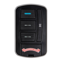
Independent Light Control
–
Controls door operator lights from inside garage
–
Energy-Saver shut-off turns off light 5 minutes after
door activation
Vacation Locking Switch
– LOCK disables controls after door is completely closed
– UNLOCK allows controls to work normally
Lighted Button
–
Shows system is powered
–
Lights when Security Lock
Switch is in UNLOCK position
–
Goes out when Security Lock
Switch is in LOCK position
1
4
2
Door Control Button
–
Open and closes door from
inside garage
3
 Loading...