WARNING
• Do Not try to remove, repair or adjust
springs or anything to which door spring
parts are fastened, such as, wood blocks,
steel brackets, cables or other like items.
Repairs and adjustments must be made by
a trained service person using proper tools
and instructions.
• Handles and other door projections can
c
atch clothing. Remove ropes, hooks,
hangers, decorative or security items
mounted to door.
• Be sure Emergency Release Cord does not
catch on roof carrier or other vehicle parts
.
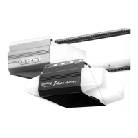
1.
Establish center line of door and header (Fig. 2-1).
• Close door.
• Measure door width. Mark center.
• Use straight edge to draw vertical line “V.”
– down door about 6”.
– on top of do
or.
– up header about 20”.
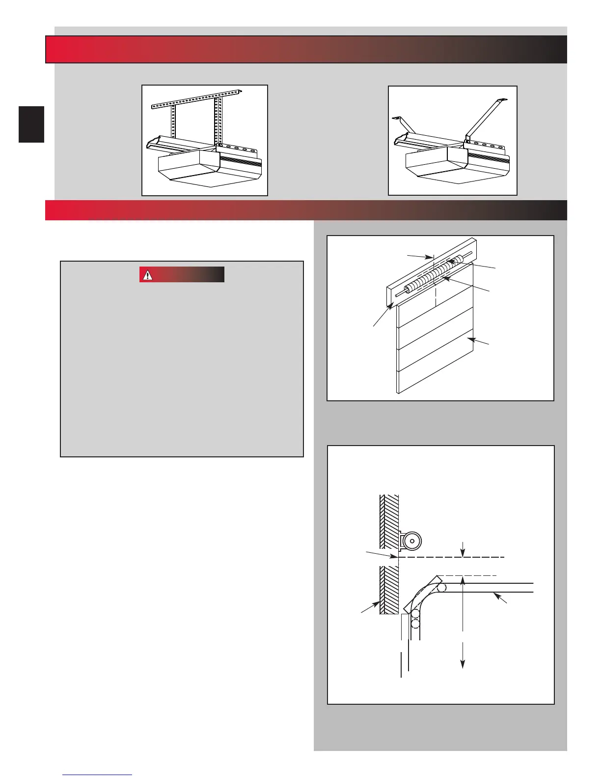
2. Establish Header Bracket position (Fig. 2-2).
• Wa
tch top edge of door as you raise it.
• Stop door when top edge reaches highest point
of tr
avel.
• Measur
e distance from top edge of door to floor.
• Add 2-1/2” to this measurement.
• Close door.
• Mar
k header at this height.
• If door spring is in the wa
y, mark header 2-1/2”
above the spring.
• Draw horizontal line “H” across line “V” at this
point (Fig 2-1).
NOTE: Header bracket must be at least 2-1/2
”
above high
point of door travel. It can be installed higher if door
spring is in the way. Do Not move the spring.
Fig. 2-2
Door
Header
Line “H”
Line “H” Can Be
Drawn Above
Spring
Fig. 2-1
Line “V”
(Vertical Center Line of
Door)
Inside of Door
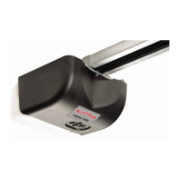
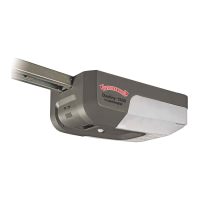
Alternate Mounting Methods
NOTE: Materials for mounting are not included
Angle Iron Method Conduit Method
Spring
Door Track
Add 2-1/2”
Minimum
Measure To Floor
High Point
Of Door Travel
Mark
Header
Here
Or
Above
Spring
Header
NOTE: Line “H” Can Be Drawn
Above Spring
Door
Line “H”
2A
...
FOR TRACK GUIDED DOORS
12
– FOR TRACKLESS DOORS GO TO PAGE 15 –
 Loading...