S3L-24P Layer 3 Lite Managed Switch Hardware Installation Guide
3
Switch components
In this chapter we’ll discuss the physical components that can be found on the front, side, and back panels
of this switch.
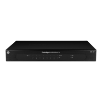
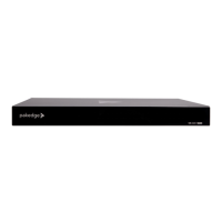
Front panel components
The front panel of this switch features only LED indicators and no physical ports or buttons.
Figure 1 Front panel
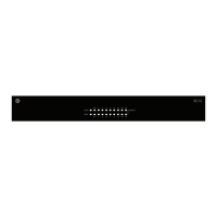
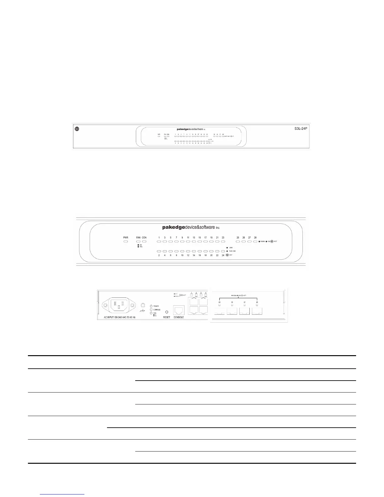
LED indicators
The front and back panels of this switch feature the following LED indicators.
Figure 2 Front panel (LED Indicators)
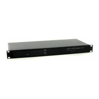
Figure 3 Back panel (LED Indicators)
The following table lists the LED indicators available on the front and back panels of the switch.
LED Indicator Color Behavior Description
Blue Solid Light Power on
Off Power off. No power cable attached.
Blue Solid Light Console is on.
Off Console is off.
Blue Solid Light Diagnostics passed. Normal operation.
Red Solid Light Fan failure.
Blue Solid Light Secure 10/100/1000 Mbps connection is active.
Blinking Packets transmitted and received.
 Loading...