S3L-24P Layer 3 Lite Managed Switch Hardware Installation Guide
4
LED Indicator Color Behavior Description
Off No active connection or port disabled.
Amber Solid Light Secure 10/100/1000 Mbps connection is active and
power is being supplied to the device in the port.
Blinking Fast blinking: Packets transmitted and received.
Slow blinking: Error supplying power.
Off No active connection or port disabled.
Link/ACT/SPEED
(SPF+ Ports)
Blue Solid Light Secure 10 Gbps connection is active.
Blinking Packets transmitted and received.
Off No active connection or port disabled.
Amber Solid Light Secure 1 Gbps connection is active.
Blinking Packets transmitted and received.
Off No active connection or port disabled.
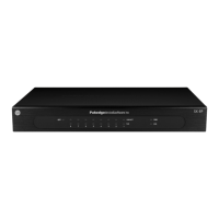
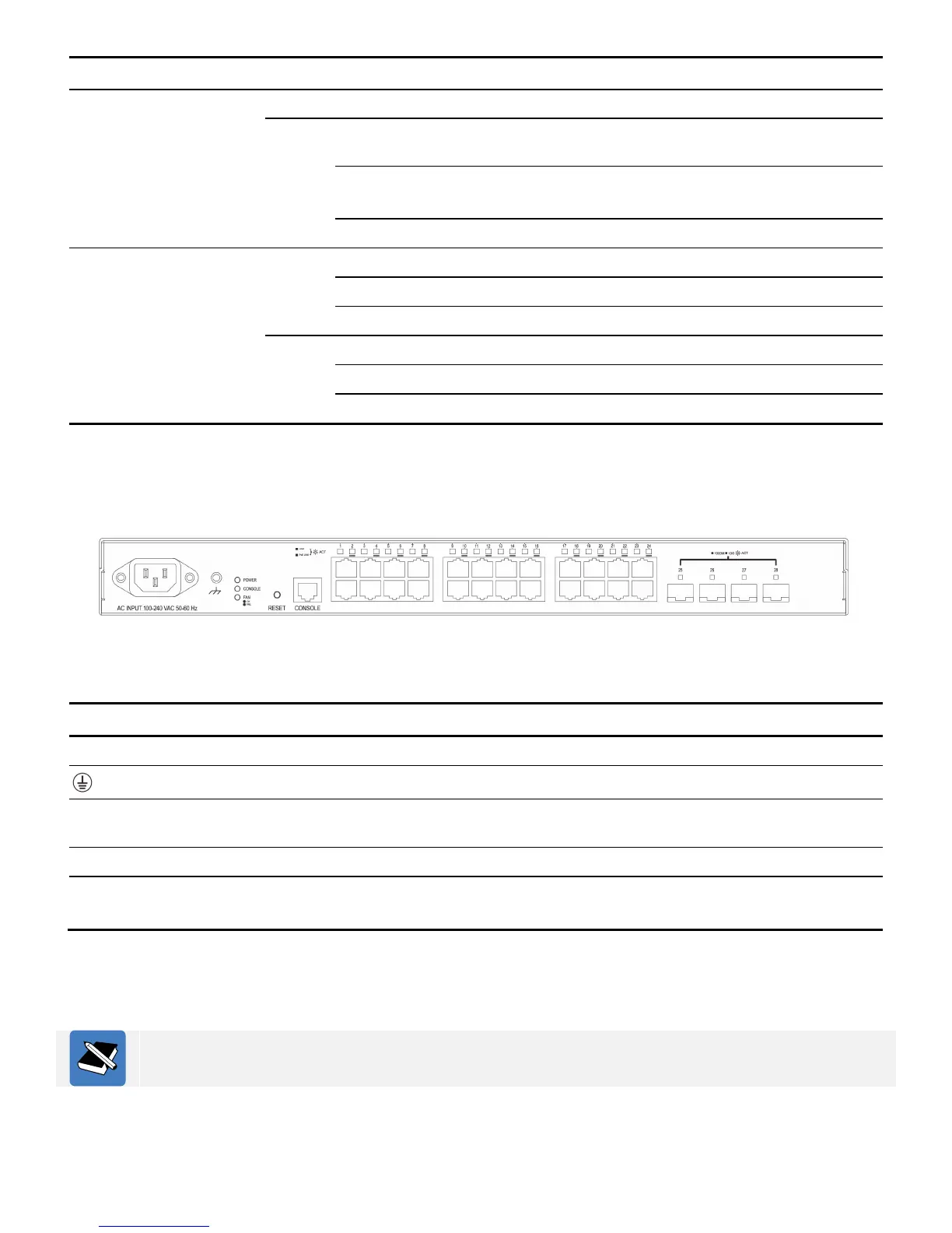
Back panel components
The back panel of this switch features the following components.
Figure 4 Back panel
The following table lists the physical ports and buttons available on the back panel of the switch.
Label Description
One AC power receptacle (IEC 60320 C14).
One electrical grounding screw.
One factory reset button within pinhole. Press and hold this button for 3 to 5 seconds to
factory reset the switch.
One out-of-band RJ45 console port
Twenty-four copper PoE ports operating at 10/100/1000 Mbps.
Four SPF+ ports operating at 1/10 Gbps.
Connect one end of the AC power cord, included in the package, into the grounded electrical outlet at the
site and insert the other end of the AC power cord into the AC power receptacle. The switch will
automatically adjust the voltage supplied to the voltage needed as this power supply supports any voltage
power supply in the range from 100VAC to 240VAC at 50Hz to 60Hz.
For more information about supported SFP+ transceivers and transceiver installation, refer to the
Installing Transceivers into the Transceiver Ports section later on.
 Loading...