6.5.3a Reconfiguring a serial interface converter
To reconfigure a serial interface converter for multi-point
wiring, complete the following steps:
1. Disconnect the main power to the electronics console
and open the cover.
WARNING!
Dangerous voltages exist within the
electronics console. Do not perform any
wiring operations until the main power to the
unit has been disconnected.
2. Remove the clear plastic shroud that covers the
electrical connectors.
3. Remove the serial interface converter mounting bracket
by removing the standoff located just below the RS232
terminal block and the grounding screw just to its left
(see figure 9).
4. Loosen the two screws that fasten the DB9 connector
to the mounting bracket, and remove the serial
interface converter from the bracket.
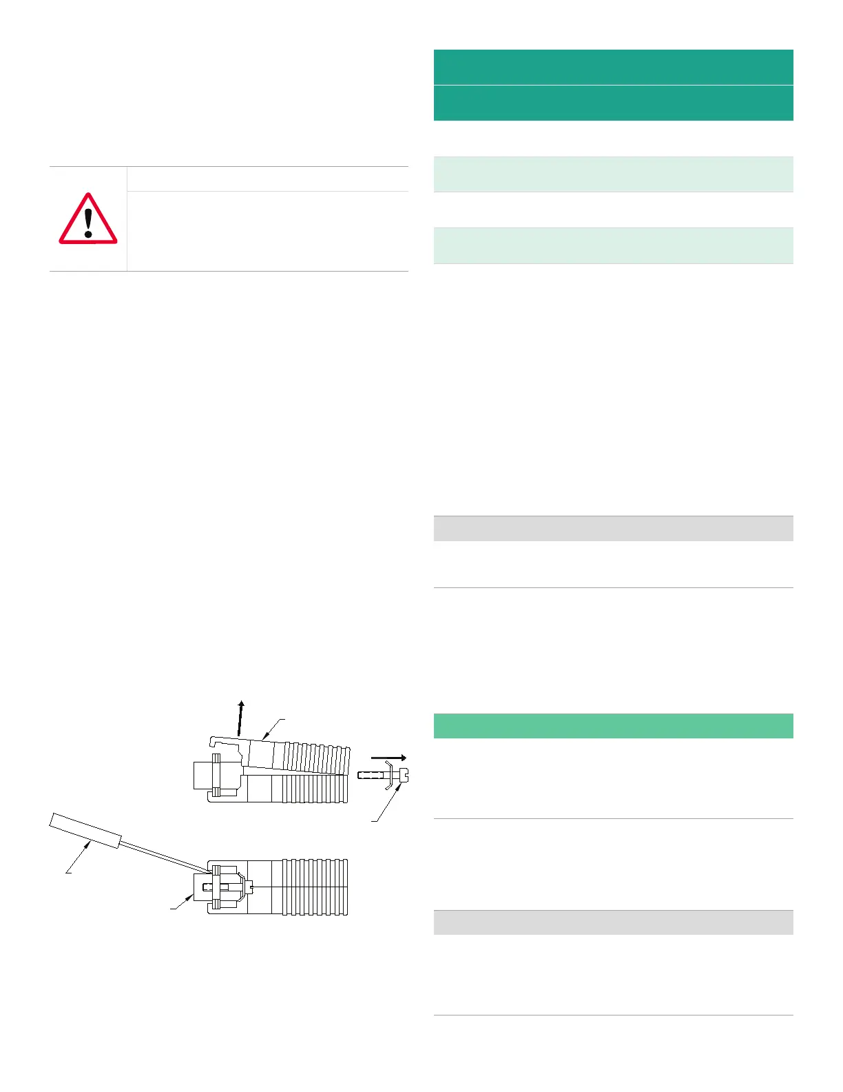
5. Use a small screwdriver to pry open the plastic case
of the serial interface converter, as shown in figure 10.
The serial interface converter contains a main printed circuit
board and a daughter printed circuit board. The daughter
board has a small terminal block attached to it and the
main board has a DIP switch (SW1) mounted near the center
of the board.
6. Locate the switch assembly on the main board, and
move the switch in position 1 from ON to OFF. The
standard ON state for this switch is for point-to-point
operation, while the OFF state is needed for multi-point
operation. See table 23 for the proper settings of all four
switches on the switch assembly.
Plastic Case
Mounting Screw
Screwdriver
Figure 10: Opening the converter case
Table 23: Switch Assembly settings
Position # Point-to-point Multi-point
1 ON OFF
2 ON ON
3 ON ON
4 OFF OFF
1. Reassemble the serial interface converter and secure it
to the mounting bracket with the two mounting screws.
2. Reinstall the mounting bracket into the electronics
enclosure and secure it with the standoff and the
grounding screw.
6.5.3b Wiring the system
After the serial interface converters have been configured
for multi-point operation, the system can be wired.
1. Using twisted-wire pairs, connect the XMT+
terminals of all the flowmeters together and connect
the XMT– terminals of all the flowmeters together.
IMPORTANT:
Make sure that the flowmeter with the non-modified
converter is wired as the last unit in the chain.
2. Using a twisted-wire pair, connect the XMT+ terminal of
the barrier strip to the T+/R+ terminal of the PC’s RS485
adapter and connect the XMT– terminal of the barrier
strip to the T-/R- terminal of the PC’s RS485 adapter
(see the documentation provided with the RS485
adapter for details).
NOTE:
The XMT+ terminal on the barrier strip is the screw
opposite the red wire connection and the XMT– terminal
on the barrier strip is the screw opposite the green wire
connection.
3. Reinstall the clear plastic shroud, close the cover to the
electronics console and reconnect the main power.
The RS485 serial interface is now ready for multi-point
operation.
IMPORTANT:
The installed version of the model GF868 software must
be version 3G or higher to support RS485 operation. If
necessary, contact the factory for information about a
software upgrade.
65








 To Next Page