6.5 The optional RS485 serial interface
Although the standard RS232 serial interface included
with the model GF868 is adequate for most applications,
Panametrics offers an optional RS485 serial interface
upgrade for special situations. The model GF868 is easily
modified to provide RS485 communications, and this
section describes the wiring and use of the special RS232
to RS485 converter.
NOTE:
For compliance with the European union’s low voltage
directive, this unit requires an external power disconnect
device such as a switch or circuit breaker. The disconnect
device must be marked as such, clearly visible, directly
accessible, and located within 1.8 m (6 ft) of the
electronics console.
6.5.1 Interface converter mounting
A special bracket containing the serial interface converter
and a three-terminal barrier strip is mounted inside the
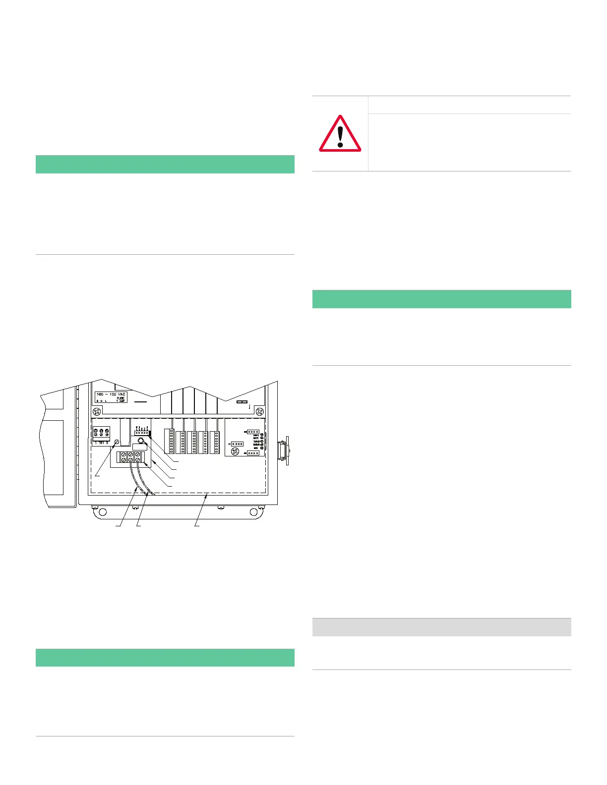
model GF868, just below the RS232 terminal block (see figure
9). The standard RS232 terminal block is wired to the input of
the serial interface converter, and the RS-485 output of the
serial interface converter is wired to the barrier strip.
RS 232
TT
TR
T
SNR
XX
CD R
DN
CHAN 1
G
I
S
GNN
S
I
R
T
R
T
UP
D
C
R
S
- XMT +
Red (XMT+)
RS232 Terminal Block
Standoff
Mounting Bracket
Barrier Strip
LVD Shroud
Green (XMT–)
Grounding
Screw
G N/L2 L1 AC
G – + DC
Figure 9: Interface converter mounting
6.5.2 Point-to-point wiring
Standard factory wiring of the RS485 serial interface is
configured for point-to-point wiring. That is, a single model
GF868 may be wired directly to a single personal computer.
To connect the RS485 serial interface, refer to figure 9 and
complete the following steps:
NOTE:
For compliance with the European union’s low voltage
directive, a transparent plastic shroud protects the
electrical connections. The shroud must remain in place,
except while wiring the unit. Reinstall the shroud after the
wiring has been completed.
1. Disconnect the main power to the electronics console
and open the cover.
WARNING!
Dangerous voltages exist within the
electronics console. Do not perform any
wiring operations until the main power to the
unit has been disconnected.
2. Remove the clear plastic shroud that covers the
electrical connectors.
3. Using a twisted-wire pair, connect the XMT+ terminal of
the barrier strip to the T+/R+ terminal of the PC’s RS485
adapter and connect the XMT– terminal of the barrier
strip to the T-/R- terminal of the PC’s RS485 adapter
(see the documentation provided with the RS485
adapter for details).
NOTE:
The XMT+ terminal on the barrier strip is the screw
opposite the red wire connection and the XMT– terminal
on the barrier strip is the screw opposite the green
wire connection.
4. Reinstall the clear plastic shroud, close the cover to the
electronics console and reconnect the main power.
The RS485 serial interface is now ready for point-to-point
operation. However, the installed version of the model GF868
software must be version 3G or higher to support RS485
operation. If necessary, contact the factory for information
about a software upgrade.
6.5.3 Multi-point wiring
The standard point-to-point wiring configuration for the
serial interface converter may be modified to permit the use
of a multi-point wiring arrangement. In a multi-point RS485
system, one flowmeter (the master) is connected to the
personal computer, while a number of additional flowmeters
(the slaves) are chained together and connected to the
master flow-meter. In order to implement such a system,
the DIP switch settings inside each serial interface converter
must be changed.
IMPORTANT:
The serial interface converter in the last slave unit in the
chain should not be reconfigured.
64










 To Next Page