Chapter 1. Installing Pipe Nozzles
24 T5 Flare Gas Transducer Installation Guide
1.3.5 Installing the First Nozzle (cont.)
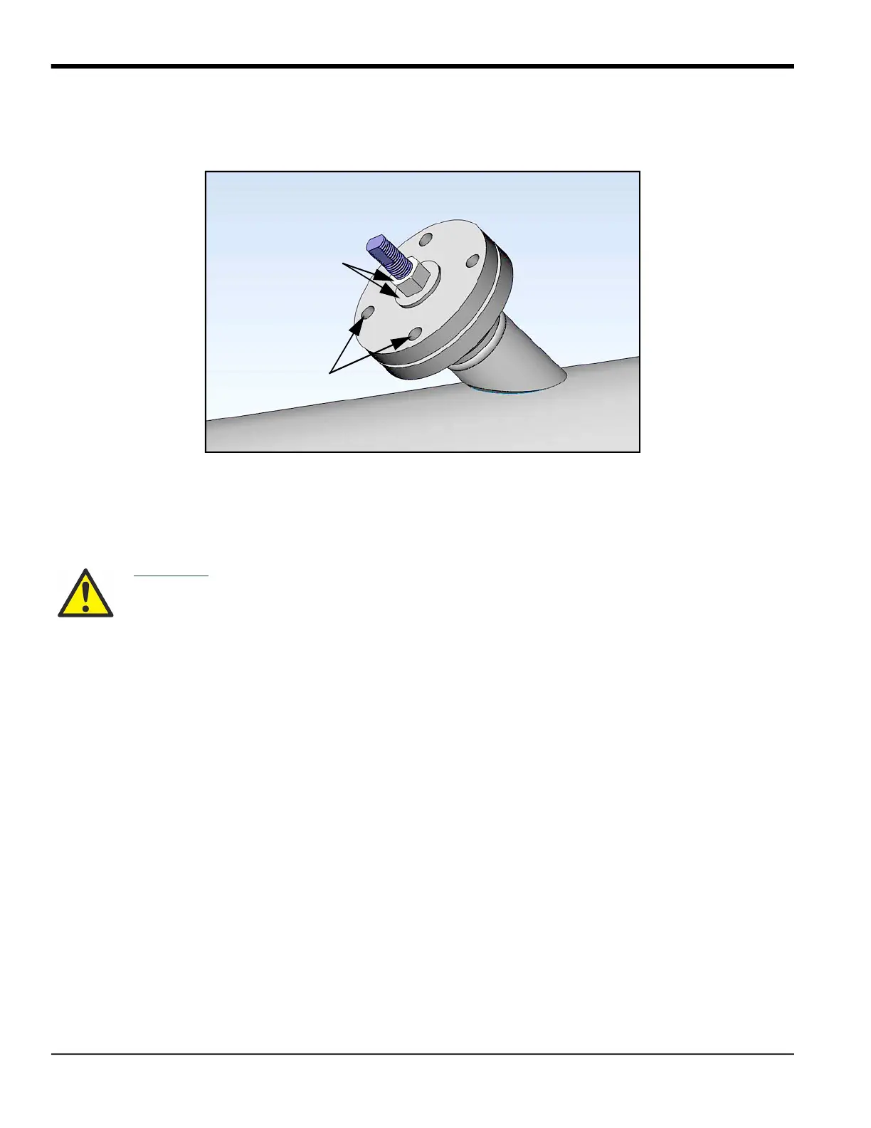
3. Align the jig bolt holes with the nozzle bolt holes. Then, tighten the assembly together, using the washer and nut
on the threaded rod.
4. The jig, boss, and nozzle assembly is designed to provide a 0.094 in. (2.4 mm) root gap between the beveled
edge of the nozzle and the outside diameter of the pipe. If this gap is not present all the way around the nozzle,
the nozzle must be removed and ground appropriately to provide the required clearance. If the root gap is larger
than the 0.094 in. (2.4 mm) dimension evenly all the way around the nozzle, then suitably sized washers may be
inserted between the jig and the nozzle to reduce the root gap dimension.
5. Tack weld the nozzle to the pipe at four diametrically opposed points, each tack being approximately
0.6 in. (15 mm) in length. Allow the weld to cool for 30 seconds between tacks.
6. Complete the root pass and subsequent filler passes as required.
7. Allow the weld to cool, and then remove the nut, washer, jig and threaded rod.
WARNING! Only qualified personnel should weld bosses and nozzles, using a suitable ASME IX
qualified welding procedure. All applicable safety codes should be observed.
Washer and Nut
Bolt Holes
 Loading...