T5 Flare Gas Transducer Installation Guide 7
Chapter 1. Installing Pipe Nozzles
1.2.2 Selecting and Marking the Pipe for Nozzle Locations (cont.)
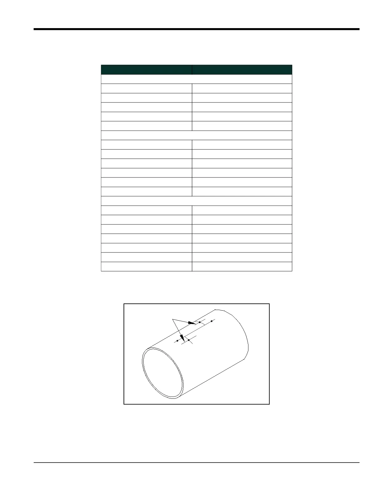
7. Scribe a 6 in. long horizontal centerline through each nozzle center location point and parallel to the original
centerline.
1.2.3 Installing the First Welding Boss
1. Each welding boss has four scribe marks indicating the center of the bias.Take one welding boss and line up its
scribe marks with the horizontal and perpendicular scribe marks on the pipe as shown below. Make sure you
position the boss on the pipe so that the contoured end of the boss matches the pipe arc. That is, the shorter side
of the boss should be closer to the original scribed pipe centerline.
Table 1: Calculated Arc Distances for Common Pipe Sizes
Pipe O.D. Arc Distance
5 in. Bias
18 in. (450 mm) 5.301 in. (134.6 mm)
24 in. (600 mm) 5.157 in. (131.0 mm)
30 in. (750 mm) 5.098 in. (129.5 mm)
36 in. (900 mm) 5.067 in. (128.7 mm)
42 in. (1050 mm) 5.048 in. (128.2 mm)
4.5 in. Bias
16 in. (400 mm) 4.779 in. (121.4 mm)
18 in. (450 mm) 4.713 in. (119.7 mm)
24 in. (600 mm) 4.613 in. (117.2 mm)
30 in. (750 mm) 4.571 in. (116.1 mm)
36 in. (900 mm) 4.549 in. (115.5 mm)
42 in. (1050 mm) 4.536 in. (115.2 mm)
3.2 in. Bias
14 in. (350 mm) 3.323 in. (84.4 mm)
16 in. (400 mm) 3.292 in. (83.6 mm)
18 in. (450 mm) 3.272 in. (83.1 mm)
24 in. (600 mm) 3.239 in. (82.3 mm)
30 in. (750 mm) 3.225 in. (81.9 mm)
36 in. (900 mm) 3.217 in. (81.7 mm)
42 in. (1050 mm) 3.213 in. (81.6 mm)


 To Next Page