Chapter 3. Installing the Transducer Assemblies
42 T5 Flare Gas Transducer Installation Guide
3.5 Aligning the Transducers (Standard Velocity Range)
For applications with gas flow velocities up to 100 m/s, align the transducers as follows:
Note:
These instructions apply to both the upstream and downstream transducer assemblies.
1. Use a straight edge to line up the alignment marks on the two barrel flanges.
2. Place the remaining bolts into the flanges and tighten them securely.
3. Place a tag on each isolation valve stating the following:
DO NOT OPERATE (CLOSE) WHEN
TRANSDUCER IS INSERTED INTO PIPE.
4. Refer to your flowmeter
Startup Guide
to make the transducer electrical connections.
3.6 Aligning the Transducers (Extended Velocity Range)
For applications with gas flow velocities up to 120 m/s, align the transducers as follows:
Note:
The downstream transducer is pre-installed at the factory in the barrel of the downstream insertion
mechanism, to shift the signal direction 6° away from the upstream transducer signal.
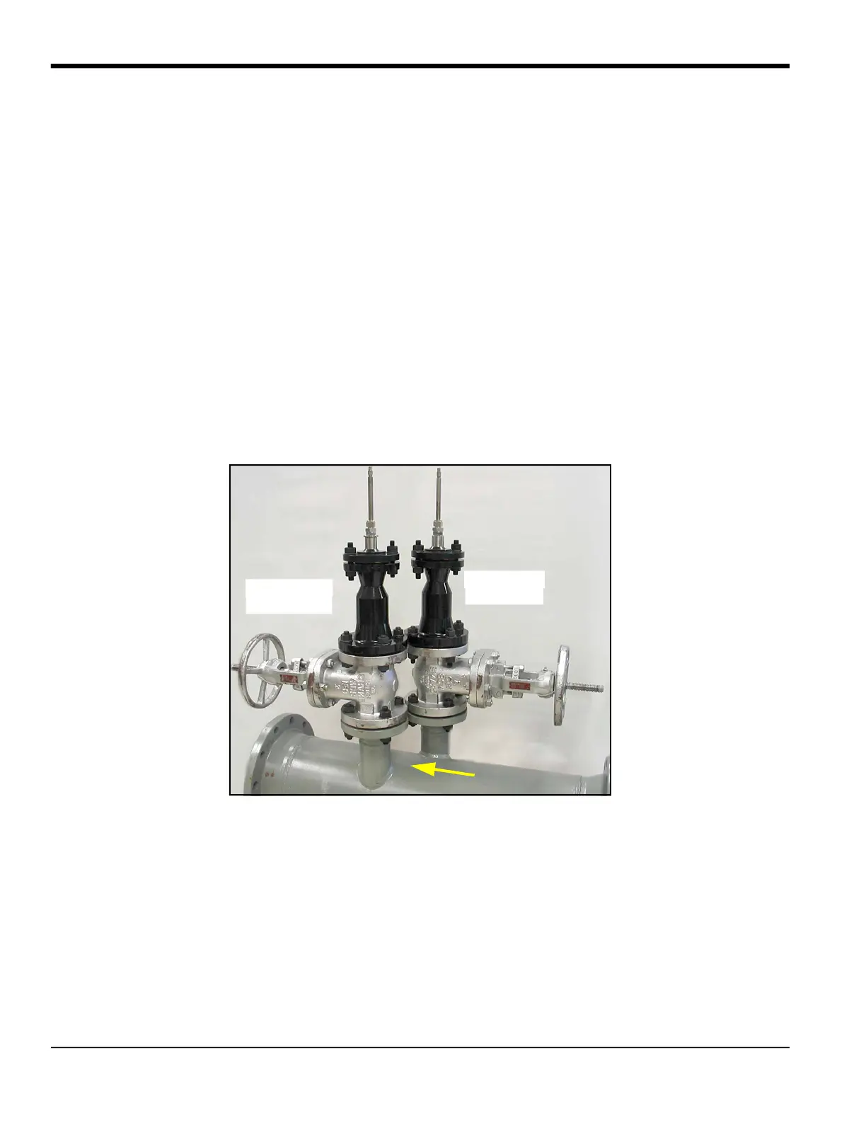
1. Verify that the downstream transducer is located on the right to a person looking from the downstream end of
the pipe (see
Figure 8
below). Contact Panametrics if the port locations do not follow this convention.
Figure 8: Extended Range Transducer Installation
Upstream
Transducer
Flow
Downstream
Transducer


 To Next Page