Chapter 2. Installing the Isolation Valves
28 T5 Flare Gas Transducer Installation Guide
2.3 Tilted 45° Installation (Extended Velocity Range)
Note:
The upstream valve and transducer are installed without wedges, as described in the previous section.
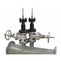
To install the downstream isolation valve, the items shown in
Figure 3
below are required.
Figure 3: Parts for 150# RF Flange Isolation Valve Installation
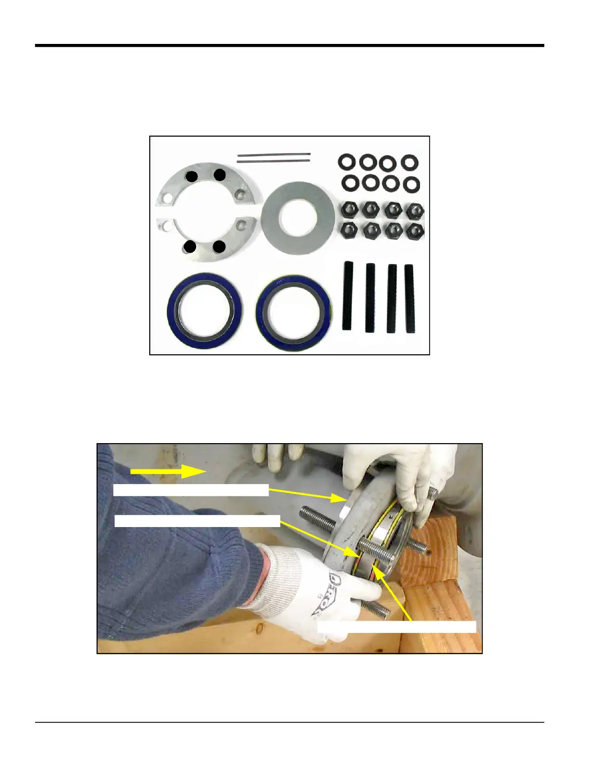
1. Insert the four bolts into the nozzle flange holes.
2. With the
Nut Side
marking facing the pipe, place the split bolt spacer halves over the bolts behind the flange, with
the thin ends corresponding to what will be the thickest side of the other wedge (see
Figure 4
below).
Note:
The wedge positions are based on the need to tilt the transducer 6° against the flow.
Figure 4: Mounting Bolts, Bolt Spacers, Wedge and Gaskets Positions
6° Wedge
Gaskets
Adjustment Screws
Hardware
Bolt Spacer
Flow Direction
Valve Face Marking on 6° Wedge
Nut Side Marking on Bolt Spacer
Nozzle Face Marking on 6° Wedge
 Loading...