Chapter 1. Installing Pipe Nozzles
16 T5 Flare Gas Transducer Installation Guide
1.3.1 Identifying and Checking the Nozzle Installation Kit Components (cont.)
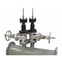
Check the markings on the end of the welding boss. The pipe OD and the mounting angle are engraved on the boss,
as shown below.
1.3.2 Selecting and Marking the First Nozzle Location
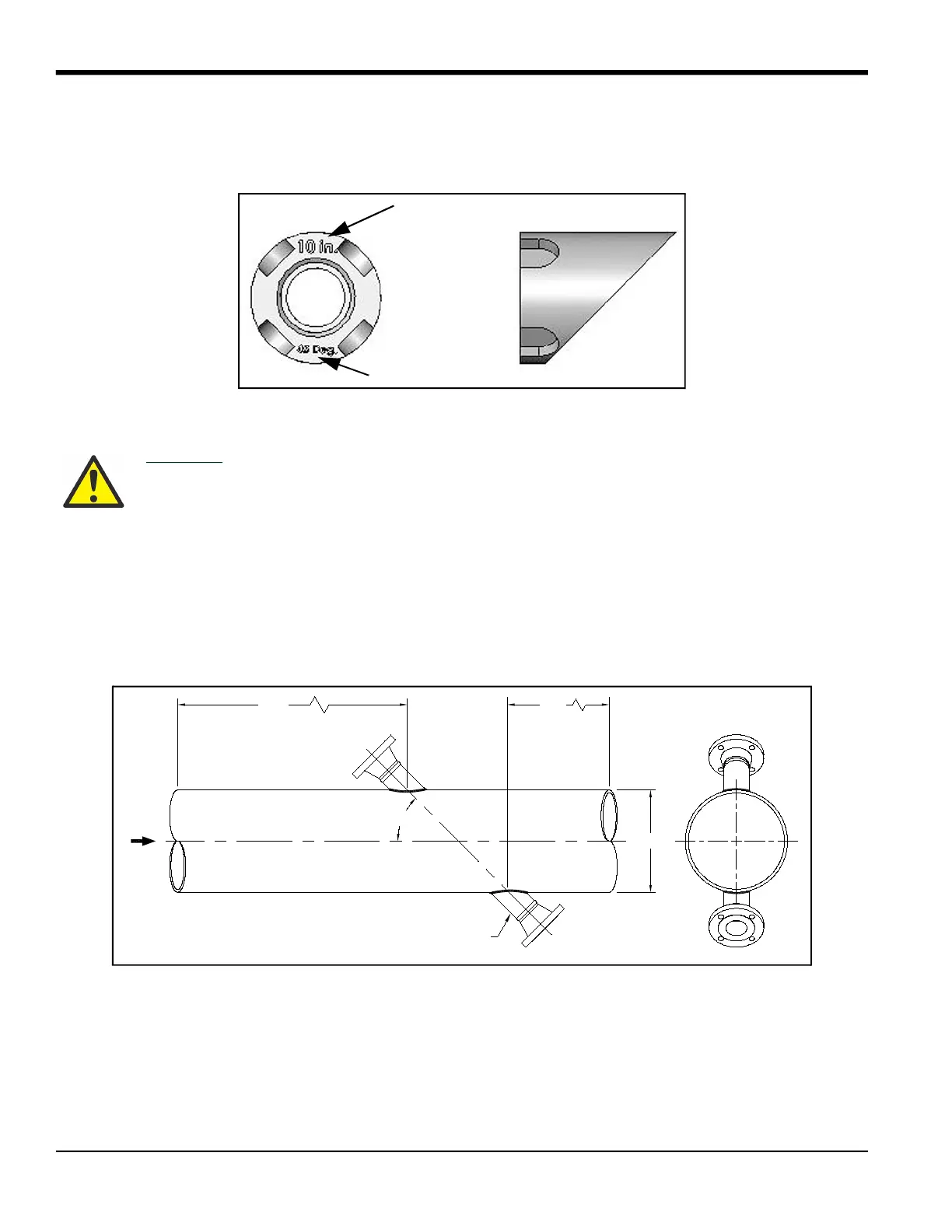
1. For optimum performance, you should select a location that has at least 20 pipe diameters of straight,
undisturbed flow upstream and 10 pipe diameters of straight, undisturbed flow downstream from the point of
measurement. Undisturbed flow means avoiding sources of turbulence such as flanges, elbows and tees;
avoiding swirl; and avoiding disturbed flow profiles. Never install the flowmeter downstream of control valves,
especially butterfly valves. If you cannot find a proper location, please consult with Panametrics
Flow Application
engineering.
CAUTION! Correct nozzle alignment is critical to the successful operation of the flowmeter.
Therefore, all marking, positioning and welding operations must be carried out with the
utmost attention to accuracy. Unless otherwise stated, dimensional positioning of the
nozzles must be held to a tolerance of 1/16 in. (±1.6 mm) relative to each other and with
respect to the pipe centerline. The angular tolerance must be held to 1
O
. All hole cutting
in process piping must be performed using hot tapping equipment.
Pipe O.D.
Mounting Angle
FLOW
NOZZLE
2 PLACES
10D
20D
D
45°
TOP VIEW
 Loading...