Chapter 1. Installing Pipe Nozzles
6 T5 Flare Gas Transducer Installation Guide
1.2.2 Selecting and Marking the Pipe for Nozzle Locations (cont.)
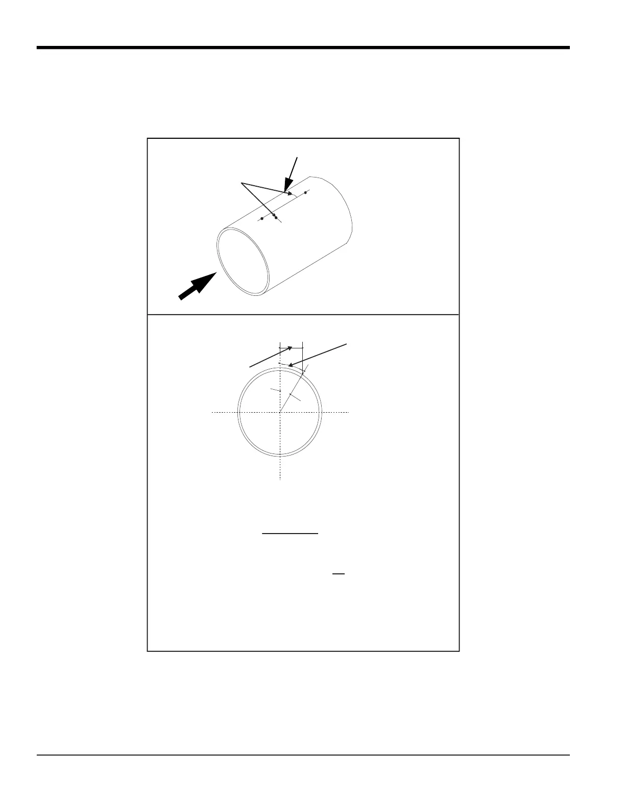
IMPORTANT: For a 3.2 in.bias distance, the downstream port must be located on the right side of the long scribe line
when viewed from the downstream end of the pipe (see the figure below). This convention is mandatory
for the 6.4 in. transducer spacing and is optional (not required) for a 10 in. or 9 in. spacing.
Punch Marks
S
L = Arc Length
along pipe
surface
R
A
Spacing
Calculate L as follows:
L = 3.142 x R x A
180
Where A = Sin
-1
R = Radius in inches
S = Bias in inches
S
R
( )
End View
Flow
Downstream Port Location
for 3.2 in. bias


 To Next Page