T5 Flare Gas Transducer Installation Guide 5
Chapter 1. Installing Pipe Nozzles
1.2.2 Selecting and Marking the Pipe for Nozzle Locations (cont.)
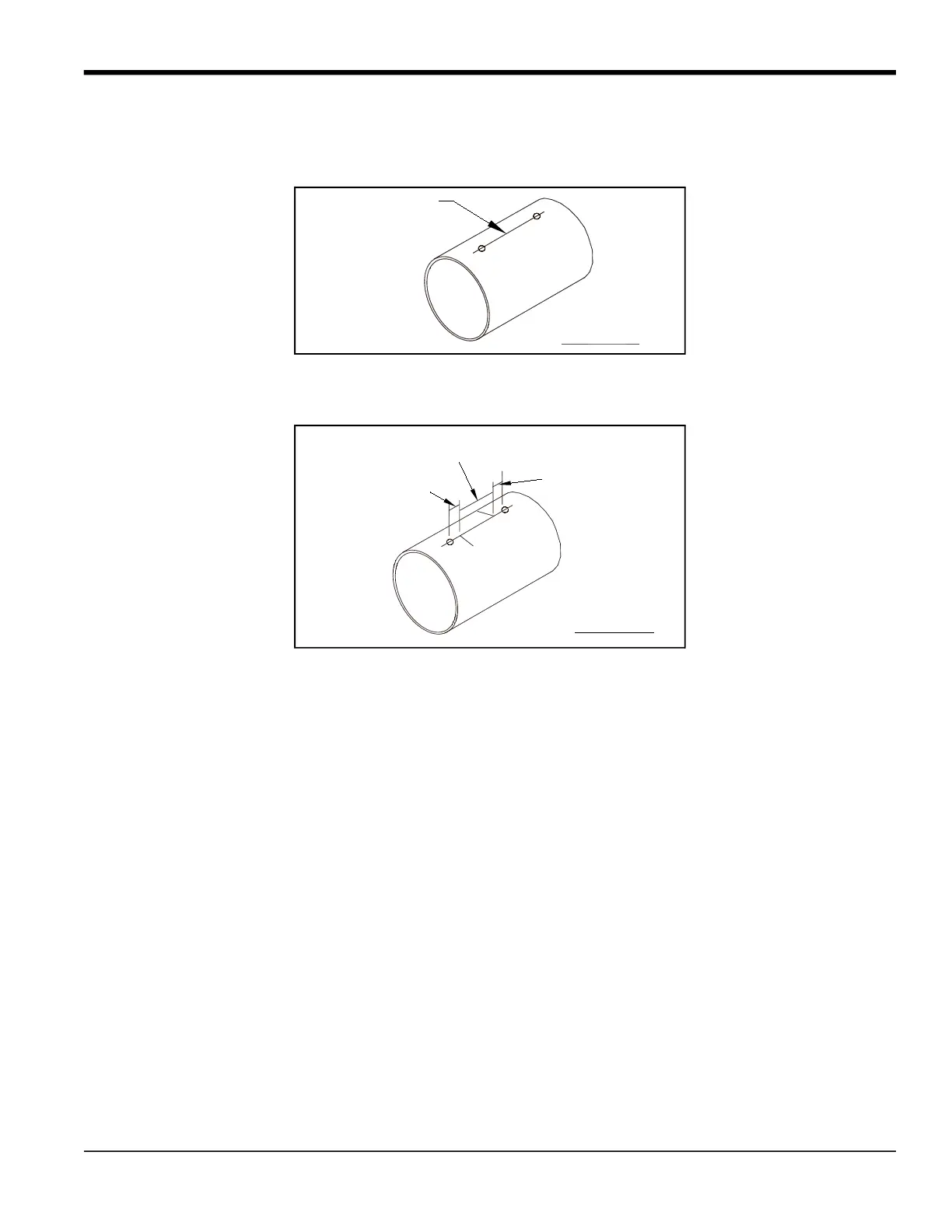
4. Spray the area between the two punch marks on the top of the pipe with a marking dye product. Using a metal
straight edge, scribe a line between the two punch marks.
5. Along the new scribe line, mark off a length equal to your transducer spacing (10 in., 9 in. or 6.4 in.) and scribe two
lines at least 10 in. in length and perpendicular to the scribe line on different sides of the scribe line.
6. Along each of the perpendicular scribe lines, lightly punch a mark at a distance equal to half of your transducer
spacing (5 in., 4.5 in. or 3.2 in.) from the center line, depending on the bias distance for your transducers. Keep in
mind that the distance along the arc of the pipe (L) from the pipe centerline is slightly greater than the
point-to-point distance through the pipe. These marks pinpoint the centers for the nozzles. Refer to
Table 1 on
page 7
for arc distances for the most commonly used pipe sizes. If your pipe size is not shown in
Table 1
, use the
equation in the figure on page 6 to calculate the arc distance.
10", 9" or 6.4"
3", 3.5" or 4.8"
3", 3.5" or 4.8"
Top View


 To Next Page