Chapter 2. Installing the Isolation Valves
30 T5 Flare Gas Transducer Installation Guide
2.3 Tilted 45° Installation (Extended Velocity Range) (cont.)
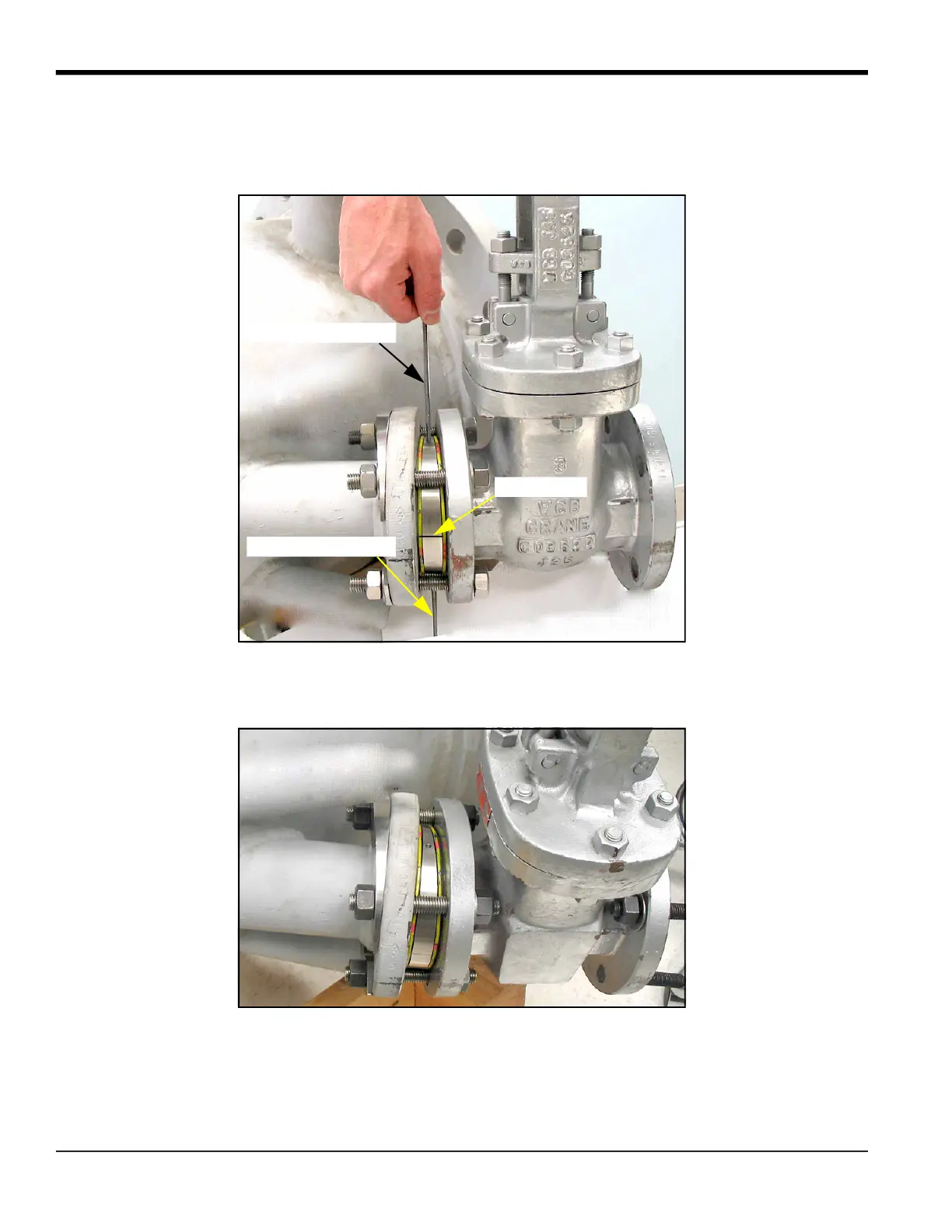
5. Insert the two adjustment screws into the threaded holes on the 6° wedge (see
Figure 6
below) and use them to
rotate the wedge until the scribe line is centered between the two bolts.
Figure 6: Adjusting the Wedge Position
6. After the wedge is positioned correctly, use two wrenches to tighten the hardware and secure the isolation valve
to the nozzle. Then remove the adjustment screws from the wedge.
Figure 7: Completed Isolation Valve Installation
Note:
The upstream valve and transducer are installed without wedges, as described in the previous section.
Adjustment Screw
Adjustment Screw
Scribe Line


 To Next Page